
Nissan Murano: Do-it-yourself / Engine oil
Nissan Murano (Z52) 2015-2024 Owners Manual / Do-it-yourself / Engine oil
 Changing engine coolant
A NISSAN dealer can change the engine
coolant. The service procedure can be
found in the NISSAN Service Manual.
Improper servicing can result in reduced
heater performance and engine overheating...
 Checking engine oil level
Park the vehicle on a level surface and
apply the parking brake.
Start the engine and let it idle until it
reaches operating temperature.
Turn off the engine...
Other information:
Nissan Murano (Z52) 2015-2024 Service Manual: B210b Str Cont Rly on Circ
DTC Description Starter control relay, integrated in IPDM E/R, permits the starter relay operation when in N (Neutral) or P (Park) position. It is installed in parallel with the starter relay.DTC DETECTION LOGICNOTE: If DTC B210B is displayed with DTC U1000, first perform the trouble diagnosis for DTC U1000...
Nissan Murano (Z52) 2015-2024 Service Manual: Working with Body Straightening Equipment
Use of Protectors Use of work clothes should be the same as for “PROTECTORS”. Refer to Protectors. Wear a safety helmet and safety shoes. When working under a Nissan Murano vehicle or when using a grinder, wear goggles. Precautions while Working To prevent danger in case the clamp slips or the panel breaks, be sure to apply a safety chain...
Categories
- Manuals Home
- Nissan Murano Owners Manual
- Nissan Murano Service Manual
- Checking engine oil level
- Indicator lights
- High Beam Assist (if so equipped)
- New on site
- Most important about car
Unfastening the seat belts. Checking seat belt operation
Unfastening the seat belts
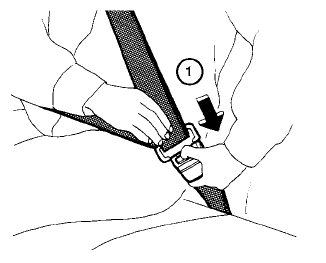
To unfasten the seat belt, press the button
on the buckle  . The seat belt
automatically
retracts.
. The seat belt
automatically
retracts.

Copyright © 2026 www.nimurano.com