Nissan Murano: Engine / Engine Mechanical :: Precaution. Precautions
The Supplemental Restraint System such as “AIR BAG” and “SEAT BELT PRE-TENSIONER”, used along with a front seat belt, helps to reduce the risk or severity of injury to the driver and front passenger for certain types of collisions.
Information necessary to service the system safely is included in the “SRS AIR BAG” and “SEAT BELT” sections of this Service Manual.
WARNING:
Always observe the following items for preventing accidental activation:
-
To avoid rendering the SRS inoperative, which could increase the risk of personal injury or death in the event of a collision that would result in air bag inflation, it is recommended that all maintenance and repair be performed by an authorized NISSAN/INFINITI dealer.
-
Improper repair, including incorrect removal and installation of the SRS, can lead to personal injury caused by unintentional activation of the system. For removal of Spiral Cable and Air Bag Module, see “SRS AIR BAG”.
-
Never use electrical test equipment on any circuit related to the SRS unless instructed to in this Service Manual. SRS wiring harnesses can be identified by yellow and/or orange harnesses or harness connectors.
PRECAUTIONS WHEN USING POWER TOOLS (AIR OR ELECTRIC) AND HAMMERS
WARNING:
Always observe the following items for preventing accidental activation:
-
When working near the Air Bag Diagnosis Sensor Unit or other Air Bag System sensors with the ignition/power switch ON or engine running, never use air or electric power tools or strike near the sensor(s) with a hammer. Heavy vibration could activate the sensor(s) and deploy the air bag(s), possibly causing serious injury.
-
When using air or electric power tools or hammers, always switch the ignition/power switch OFF, disconnect the 12V battery or batteries, and wait at least 3 minutes before performing any service.
-
Drain engine coolant and engine oil after the engine has cooled completely.
When performing the procedure after removing cowl top cover, cover the lower end of windshield with urethane, etc to prevent damage to windshield.

-
Use an angle wrench for the final tightening of the following engine parts:
-
Cylinder head bolts
-
Main bearing cap bolts
-
Connecting rod cap nuts
-
Crankshaft pulley bolt (No angle wrench is required as the bolt flange is provided with notches for angular tightening)
-
-
Do not use a torque value for final tightening.
-
The torque value for these parts are for a preliminary step.
-
Ensure thread and seat surfaces are clean and coated with engine oil.
-
Before starting work, make sure no fire or spark producing items are in the work area.
-
Release fuel pressure before disassembly.
-
After disconnecting pipes, plug openings to stop fuel leaks.
-
Thoroughly inspect parts before repairing or replacing them, even if they are new. Replace as necessary.
-
When instructed to use special service tools, use the specified tools. Always be careful to work safely, avoid forceful or uninstructed operations.
-
Exercise maximum care to avoid damage to mating or sliding surfaces.
-
Cover openings of engine system with tape or the equivalent, if necessary, to seal out foreign materials.
-
Mark and arrange disassembly parts in an organized way for easy troubleshooting and assembly.
-
When loosening nuts and bolts, as a basic rule, start with the one furthest outside, then the one diagonally opposite, and so on. If the order of loosening is specified, do exactly as specified. Power tools may be used where noted in the step.
-
Use torque wrench to tighten bolts or nuts to specification.
-
When tightening nuts and bolts, as a basic rule, equally tighten in several different steps starting with the ones in center, then ones on inside and outside diagonally in this order. If the order of tightening is specified, do exactly as specified.
-
Replace with new gasket, packing, oil seal or O-ring.
-
Dowel pins are used in several critical parts for correct alignment. When replacing and reassembling parts with dowel pins, check that dowel pins are installed in their original positions.
-
Thoroughly wash, clean, and air-blow each part. Carefully check oil or coolant passages for any restriction and blockage.
-
Avoid damaging sliding or mating surfaces. Completely remove foreign materials such as cloth lint or dust. Before assembly, oil sliding surfaces well.
-
Release air within route when refilling after draining coolant.
-
Before starting engine, apply fuel pressure to fuel lines with turning ignition switch ON (with engine stopped). Then make sure that there are no leaks at fuel line connections.
-
After repairing, start engine and increase engine speed to check coolant, fuel, oil, and exhaust systems for leaks.
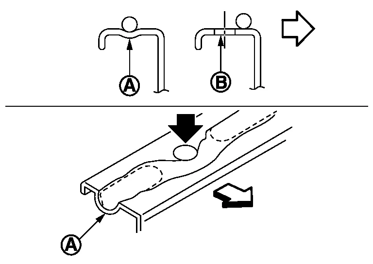
Handling and disposal of sodium-filled exhaust valves requires special care and consideration. Under conditions such as breakage with subsequent contact with water, metal sodium which lines the inner portion of exhaust valve will react violently, forming sodium hydroxide and hydrogen which may result in an explosion. Sodium-filled exhaust valve is identified on the top of its stem as shown in illustration.
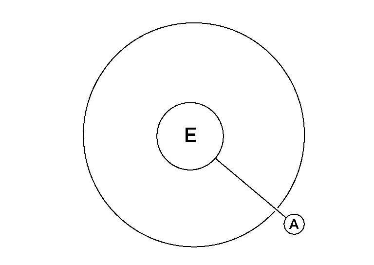
| (A) | : Identification mark of sodium-filled exhaust valve |
DEALER DISPOSAL INSTRUCTIONS
CAUTION:
-
Use approved shatter-resistant eye protection when performing this procedure.
-
Perform this and all subsequent disposal work procedures in an open room, away from flammable liquids. Keep a fire extinguisher, rated at least 10 ABC, in close proximity to the work area.
-
Be sure to wear rubber gloves when performing the following operations.
-
Make sure the resultant (high alkalinity) waste water does not contact your skin. If the waste water does contact you, wash the contacted area immediately with large quantities of water.
-
Dealers should check their respective state and local regulations concerning any chemical treatment or waste water discharge permits which may be required to dispose of the resultant (high alkalinity) waste water.
-
Clamp valve stem in a vice.
-
The valve has a specially-hardened surface. To cut through it, first remove a half-round section, approximately 30 mm (1.18 in) long using air-powered grinder until black color is removed and silver color appears.
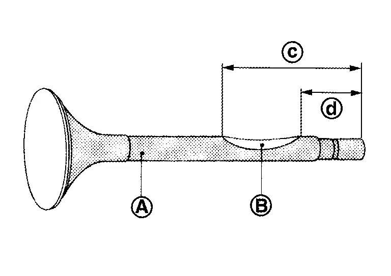
(A) : Black color (B) : Silver color (c) : 47 mm (1.85 in) (d) : 17 mm (0.67 in) -
Use hacksaw to cut through approximately half the diameter of valve stem. Make the serration at a point 40 mm (1.57 in) from the end of valve stem.
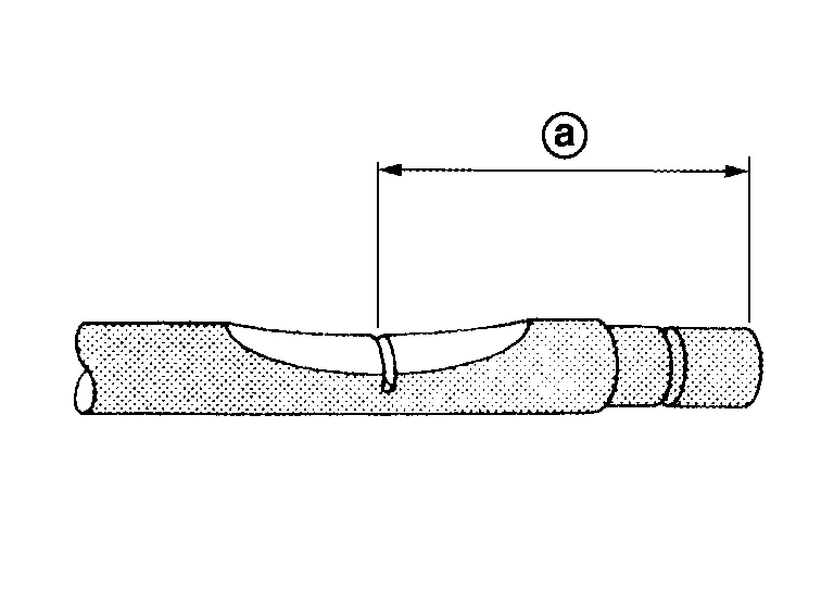
(a) : 40 mm (1.57 in) -
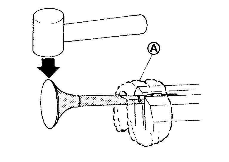
Cover the serrated end of the valve with a large shop towel (A). Strike the valve face end with a hammer, separating it into two pieces.
-
Fill a bucket, such as a 20
 (5-1/4 US gal, 4-3/8 Imp gal) oil can, with at least 10 (2-5/8 US gal, 2-1/4 lmp gal) of water. Carefully place the already cut (serrated) valves into the water one-at-a-time using a set of large tweezers and quickly move away at least 2.7 m (9 ft).
 -
The valves should be placed in a standing position as shown in the illustration to allow complete reaction. After the bubbling action has subsided, additional valves can be placed into the bucket allowing each subsequent chemical reaction to subside. However, no more than eight valves should be placed in the same 10
(2-5/8 US gal, 2-1/4 lmp gal) amount of water. The complete chemical reaction may take as long as four to five hours. Remove the valves using a set of large tweezers after the chemical reaction has stopped. Afterwards, valves can be disposed as ordinary scrap.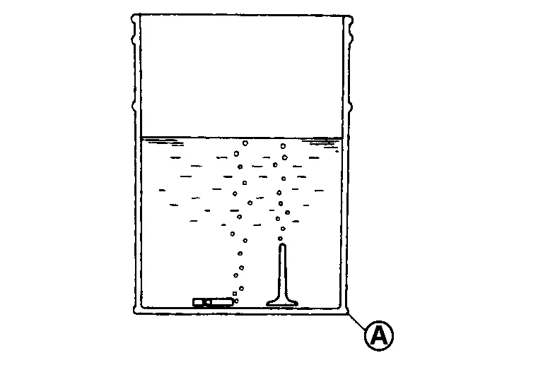
(A) : Bucket [Such as 20 (5-1/4 US gal, 4-3/8 Imp gal) oil can]
REMOVAL OF LIQUID GASKET SEALING
CAUTION:
Do not damage the mating surfaces.
-
After removing the bolts and nuts, separate the mating surface and remove the liquid gasket using Tool (A).
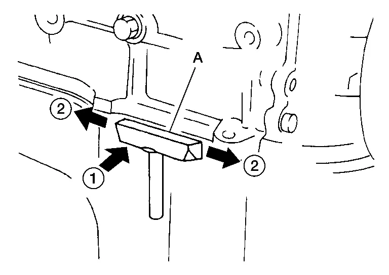
Tool number (A) : KV10111100 (J-37228) -
In areas where the cutter is difficult to use, use a plastic hammer to lightly tap (1) the cutter where the liquid gasket is applied. Use a plastic hammer to slide (2) the cutter by tapping on the side.
LIQUID GASKET APPLICATION PROCEDURE
-
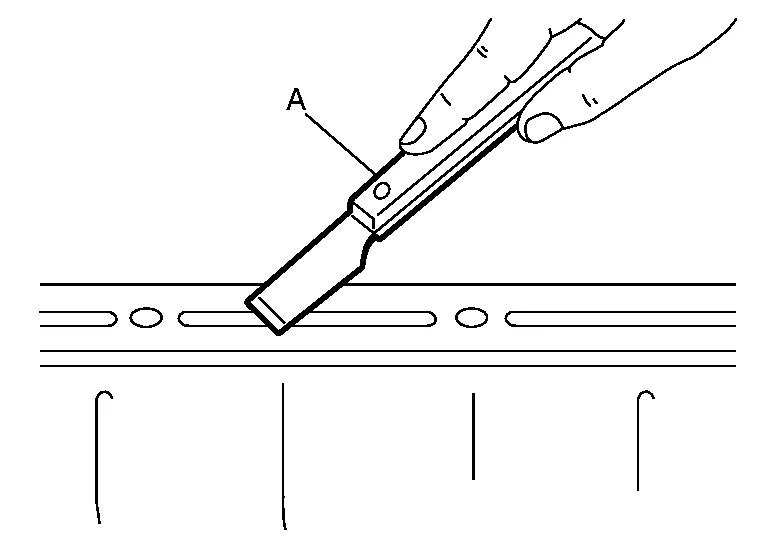
Using suitable tool (A), remove old liquid gasket adhering to the liquid gasket application surface and the mating surface.
-
Remove liquid gasket completely from the groove of the liquid gasket application surface, bolts, and bolt holes.
-
-
Thoroughly clean the mating surfaces and remove adhering moisture, grease and foreign materials.
-
Attach liquid gasket tube to the suitable tool.
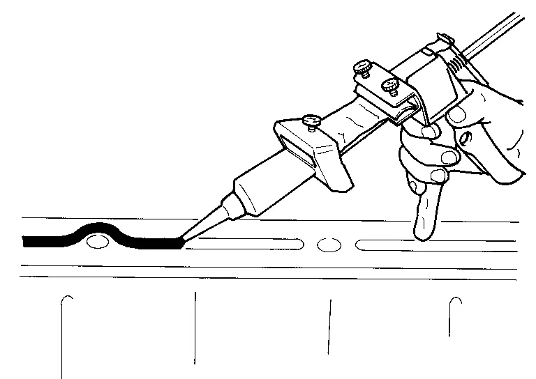
Use Genuine Silicone RTV Sealant, or equivalent. Refer to Recommended Chemical Products and Sealants.
-
Apply liquid gasket without gaps to the specified location according to the specified dimensions.
-
If there is a groove for liquid gasket application, apply liquid gasket to the groove.
-
As for bolt holes (B), normally apply liquid gasket inside the holes. Occasionally, it should be applied outside the holes. Check to read the text of this manual.
(A) : Groove 
: Inside -
Within five minutes of liquid gasket application, install the mating component.
-
If liquid gasket protrudes, wipe it off immediately.
-
Do not retighten bolts or nuts after the installation.
-
After 30 minutes or more have passed from the installation, fill engine oil and engine coolant. Refer toChanging Engine Oil and Changing Engine Coolant.
-
CAUTION:
If there are more specific instructions in the procedures contained in this manual concerning liquid gasket application, observe them.
 Engine
..
 Engine Mechanical :: Preparation. Preparation
Special Service Tools
The actual shape of the tools may differ from those illustrated here.
Tool number
(TechMate No.)
Tool name Description
—
(J-43897-18)
Oxygen sensor thread cleaner
Reconditioning the exhaust system threads before installing a new oxygen sensor (Use with anti-seize lubricant shown below...
Other information:
Nissan Murano (Z52) 2015-2024 Service Manual: Condenser
Exploded View 1. Condenser upper bracket (RH) 2. Condenser pipe assembly 3. Refrigerant pressure sensor 4. Condenser lower bracket (RH) 5. Condenser (includes liquid tank) 6. Condenser lower bracket (LH) 7. Condenser upper bracket (LH) Removal and Installation REMOVALDischarge the refrigerant...
Nissan Murano (Z52) 2015-2024 Service Manual: B1383 Incomp Steering Angle Sensor Adjust
DTC Description DTC DETECTION LOGIC DTC No. CONSULT screen terms (Trouble diagnosis content) DTC detection condition B1383–01 Incomp steering angle senor adjust (Steering angle sensor calibration) Diagnosis condition When ignition switch is ON...
Categories
- Manuals Home
- Nissan Murano Owners Manual
- Nissan Murano Service Manual
- How to enable/disable the LDW system
- System malfunction
- Memory storage function (key-link)
- New on site
- Most important about car
Seatback pockets

Theremaybe one or two seatback pockets located on the back of the driver and passenger seats. The pockets can be used to store maps.
WARNING