Nissan Murano: Audio, Visual & Navigation System :: Display Audio System - With 8" Color Display / Ecu Diagnosis Information. Audio Unit
 NOTE:
NOTE:
The following table includes information (items) inapplicable to this Nissan Murano vehicle. For information (items) applicable to this vehicle, refer to CONSULT display items.
| Monitor Item | Condition | Value/Status |
|---|---|---|
| Sunload sensor | — | Off |
| — | On | |
| Parking brake | Parking brake not applied. | Off |
| Parking brake applied. | On | |
| IGN SIG | Ignition switch OFF. | Off |
| Ignition switch ON. | On | |
| Auto ACC | Auto accessory mode OFF. | Off |
| Auto accessory mode ON. | On | |
| ACC | Accessory mode OFF. | Off |
| Accessory mode ON. | On | |
| Aux IN 1 | Accessory not connected to aux in jack. | Off |
| Accessory connected to aux in jack. | On | |
| Aux IN 2 | Accessory not connected to USB. | Off |
| Accessory connected to USB. | On | |
| REV SIG | Selector lever in any position other than R. | Off |
| Selector lever in R position. | On | |
| ILLUM SIG | Illumination signal not received. | Off |
| Illumination signal received. | On | |
| Illumination Control | Illumination control signal not received. | Off |
| Illumination control signal received. | On |
TERMINAL LAYOUT
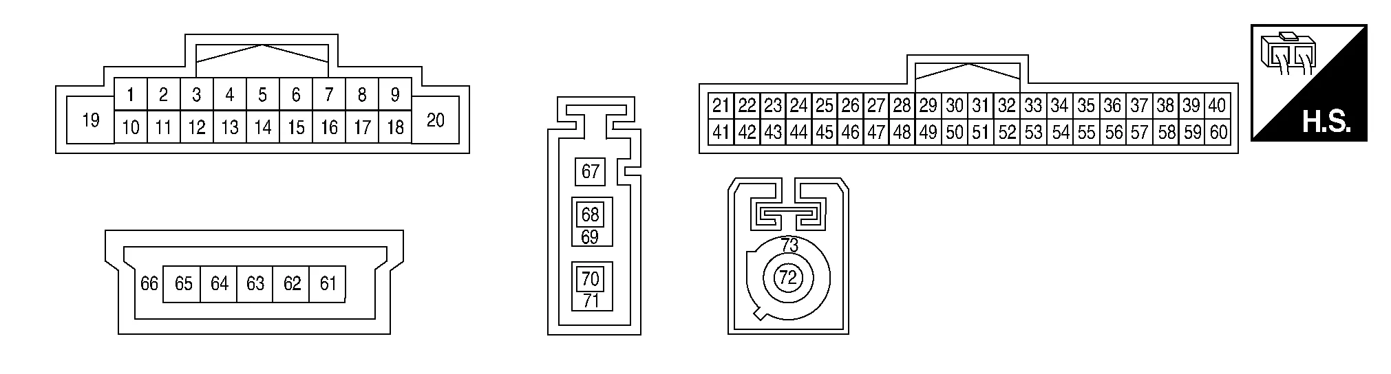
PHYSICAL VALUES
|
Terminal (Wire color) | Description | Condition |
Reference value (Approx.) | |||
|---|---|---|---|---|---|---|
| + | – | Signal name | Input/Output | Ignition switch | Operation | |
|
2 (P) |
3 (W) |
Sound signal front LH | Output | ON | Sound output |
|
|
4 (G) |
5 (W) |
Sound signal rear LH | Output | ON | Sound output |
|
|
7 (P) |
Ground | ACC power supply | Input | ON | — | Battery voltage |
|
8 (G) |
Ground | Reverse signal | Input | ON | Selector lever in R (reverse) | Battery voltage |
| Selector lever in any position other than R (reverse) | 0 V | |||||
|
11 (G) |
12 (W) |
Sound signal front RH | Output | ON | Sound output |
|
|
13 (R) |
14 (P) |
Sound signal rear RH | Output | ON | Sound output |
|
|
17 (LG) |
Ground | Ignition power supply | Input | ON | — | Battery voltage |
|
19 (G) |
Ground | Battery power supply | Input | OFF | — | Battery voltage |
|
20 (B) |
Ground | Ground | — | ON | — | 0 V |
|
21 (L) |
— | CAN-High | Input/Output | — | — | — |
|
22 (SB) |
— | AV communication high | Input/Output | — | — | — |
|
23 (SB) |
— | AV communication high | Input/Output | — | — | — |
|
28 (R) |
Ground | Camera power supply | Output | ON | Camera image displayed | 6.0 V |
| Except for above | 0 V | |||||
|
29 (B) |
Ground | Camera ground | — | ON | — | 0 V |
|
33 (B) |
Ground | AUX ground | — | ON | — | 0V |
|
34 (R) |
Ground | AUX audio signal RH | Input | ON | Received audio signal (AUX input) |
|
|
39 (W) |
Ground | MIC VCC | Output | ON | — | 5 V |
|
40 (B) |
59 (Shield) |
Microphone signal | Input | ON | While speaking into microphone. |
|
|
41 (P) |
— | CAN-Low | Input/Output | — | — | — |
|
42 (LG) |
— | AV communication low | Input/Output | — | — | — |
|
43 (LG) |
— | AV communication low | Input/Output | — | — | — |
|
49 (B)1 (W)2 |
48 (Shield) |
Camera image signal | Input | ON | Camera image displayed |
|
|
51 (W) |
— | HF/VR mode change | — | — | — | — |
|
53 (Shield) |
— | AUX signal shield | — | — | — | — |
|
54 (W) |
Ground | AUX audio signal LH | Input | ON | Received audio signal (AUX input) |
|
|
58 (R) |
9 (B) |
Illumination control signal | Input | ON | Headlamps ON | Battery voltage |
|
61 (B) |
— | USB ground | — | — | — | — |
|
63 (G) |
— | USB D+ signal | — | — | — | — |
|
64 (W) |
— | USB D− signal | — | — | — | — |
|
65 (R) |
— | V BUS signal | — | — | — | — |
|
66 (Shield) |
— | USB shield | — | — | — | — |
|
67 (B) |
Ground | Antenna amp. ON signal | Output | ON | Audio unit ON, FM-AM selected. | Battery voltage |
|
68 (B) |
Ground | AM/FM antenna signal | Input | ON | Audio unit ON, FM-AM selected. | 5.0 V |
|
69 (Shield) |
— | AM/FM antenna shield | — | — | — | — |
|
72 (B) |
Ground | Satellite antenna signal | Input | ON | Audio unit ON, XM selected. | 5.0 V |
|
73 (Shield) |
— | Satellite antenna shield | — | — | — | — |

1: With Intelligent around view monitor system
2: Without Intelligent around view monitor system
| DTC | Audio unit operation in fail-safe mode |
|---|---|
| B1305-04 | Audio unit internal error |
| B130B-11 | Rear door speaker RH inoperative |
| B130B-12 | |
| B130B-13 | |
| B130B-1C | |
| B130D-11 |
|
| B130D-12 | |
| B130D-13 | Front door speaker RH inoperative |
| B130D-1C |
|
| B130F-11 |
|
| B130F-12 | |
| B130F-13 | Front door speaker LH inoperative |
| B130F-1C |
|
| B1311-11 | Rear door speaker LH inoperative |
| B1311-12 | |
| B1311-13 | |
| B1311-1C | |
| B1315-11 | No AM/FM radio reception |
| B1315-13 | |
| B1317-11 | No satellite radio reception |
| B1317-13 | |
| B1321-13 | Instrument panel tweeter RH inoperative |
| B1322-13 | Instrument panel tweeter LH inoperative |
| B1328-11 | Microphone is inoperative |
| B1328-12 | |
| B1328-13 | |
| B132A-01 | USB is inoperative |
| B132A-13 | |
| B132A-49 | |
| B1339-8F | Rear view camera is inoperative |
| B133A-8F | Camera image is inoperative |
| B1341-16 | Battery protection shuts audio unit down 60 seconds after low voltage condition |
| B1341-17 |
|
| B1341-49 | Audio unit internal failure |
| B1341-55 | Audio unit configuration error |
| B1341-98 | Audio unit shuts down after 5 seconds |
| B1342-62 | Audio and visual system features are unavailable |
| B1343-41 | Audio unit ROM error |
| B1344-41 | Audio unit EEPROM error |
| B1347-49 | Bluetooth® function inoperative |
| B1351-4B | Audio unit shuts down and cannot restart for more than 5 minutes |
| B1356-49 | Audio unit DSP error |
| B135E-49 | Audio unit fan error |
| B1360-02 | Steering switch is inoperative |
| B1375-11 | Rear view camera is inoperative |
| B1375-12 | |
| B1375-13 | |
| B1380-49 | Wi-fi function is inoperative |
| B1383-01 | Predictive course line is not displayed |
| B13CF-73 | Audio unit buttons error |
| B13D9-8F | USB devices connected to front auxiliary input jacks are inoperative |
| U0079-00 | CAN communication does not function |
| U1000-01 | Function of CAN communication signals received by Audio unit are inoperative |
| U1300-01 | AV communication is inoperative |
If multiple DTCs are detected simultaneously, check them one by one depending on the following DTC inspection priority chart.
| Priority | Detected items (DTC) |
|---|---|
| 1 |
|
| 2 |
|
| 3 |
|
| CONSULT Display | Reference Page |
|---|---|
| B1305-04: Control unit internal error | DTC Description |
| B130B-11: Rear RH speaker | DTC Description |
| B130B-12: Rear RH speaker | |
| B130B-13: Rear RH speaker | |
| B130B-1C: Rear RH speaker | |
| B130D-11: Front RH speaker | DTC Description |
| B130D-12: Front RH speaker | |
| B130D-13: Front RH speaker | |
| B130D-1C: Front RH speaker | |
| B130F-11: Front LH speaker | DTC Description |
| B130F-12: Front LH speaker | |
| B130F-13: Front LH speaker | |
| B130F-1C: Front LH speaker | |
| B1311–11: Rear LH speaker | DTC Description |
| B1311–12: Rear LH speaker | |
| B1311–13: Rear LH speaker | |
| B1311–1C: Rear LH speaker | |
| B1315–11: AM/FM 1 antenna | DTC Description |
| B1315–13: AM/FM 1 antenna | |
| B1317–11: XM antenna connection | DTC Description |
| B1317–13: XM antenna connection | |
| B1321–13: Front right tweeter | DTC Description |
| B1322–13: Front left tweeter | DTC Description |
| B1328–11: External Microphone 1 | DTC Description |
| B1328–12: External Microphone 1 | |
| B1328–13: External Microphone 1 | |
| B132A-01: External USB | DTC Description |
| B132A-13: External USB | |
| B132A-49: External USB | |
| B1339–8F: Rear camera connection | DTC Description |
| B133A–8F: AVM connection | DTC Description |
| B1341–16: Head unit | DTC Description |
| B1341–17: Head unit | |
| B1341–49: Head unit | |
| B1341–55: Head unit | |
| B1341–98: Head unit | |
| B1342–62 Locked system | DTC Description |
| B1343–41 ECU Rom | DTC Description |
| B1344–41 ECU EEPROM | DTC Description |
| B1347–49 ECU Bluetooth module | DTC Description |
| B1351–4B: ECU Amplifier | DTC Description |
| B1356–49 ECU DSP | DTC Description |
| B135E–49 ECU Fan | DTC Description |
| B1360–02: Combination meter | DTC Description |
| B1375–11: Rear camera Power supply | DTC Description |
| B1375–12: Rear camera Power supply | |
| B1375–13: Rear camera Power supply | |
| B1380–49 ECU Wifi module | DTC Description |
| B1383–01: Incomp steering angle sensor adjust | DTC Description |
| B13CF-73: Buttons | DTC Description |
| B13D9–8F: USB communication error | DTC Description |
| U0079–00: Control module communication Bus G Off | DTC Description |
| U1000–01: CAN COMM CIRCUIT | DTC Description |
| U1300–01: AV communication circuit | DTC Description |
 Diagnosis System (audio Unit)
Description
The audio unit on board diagnosis performs the following functions listed in the table below: Mode Description
Self Diagnosis
Audio system diagnosis...

Other information:
Nissan Murano (Z52) 2015-2024 Owners Manual: Chassis & body maintenance
Abbreviations: I = Inspect and correct or replace as necessary, R = Replace, NOTE: Maintenance items with “ ” should be performed more frequently according to “Maintenance under severe driving conditions”. (1) If towing a trailer, using a camper or a car-top carrier or driving on rough or muddy roads, inspect CVT fluid deterioration every 60,000 miles (96,000 km), then change CVT fluid if necessary...
Nissan Murano (Z52) 2015-2024 Owners Manual: Hood
Pull the hood lock release handle located below the driver side instrument panel until the hood springs up slightly. Locate the lever in between the hood and grille and push the lever sideways with your fingertips and raise the hood ...
Categories
- Manuals Home
- Nissan Murano Owners Manual
- Nissan Murano Service Manual
- GAS STATION INFORMATION
- Jacking up vehicle and removing the damaged tire
- Settings
- New on site
- Most important about car
Fuel gauge

The gauge indicates the approximate fuel level in the tank.
The gauge may move slightly during braking, turning, acceleration, or going up or down hills.
The gauge needle returns to 0 (Empty) after the ignition switch is placed in the OFF position.