Nissan Murano: General Information :: Basic Inspection / Consult Checking System
 NOTE:
NOTE:
This vehicle is diagnosed using CONSULT-III plus
-
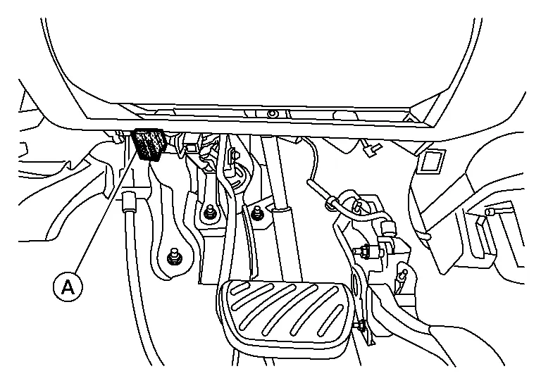
When CONSULT is connected with a data link connector (A) equipped on the vehicle side, it will communicate with the control unit equipped in the Nissan Murano vehicle and then enable various kinds of diagnostic tests.
-
Refer to CONSULT-III plus Software Operation Manual for more information.
FUNCTION
| Mode | Function |
|---|---|
| All DTC Reading | Display all DTCs or diagnostic items that all ECUs are recording and judging. |
| Work support | This mode enables a technician to adjust some devices faster and more accurately. |
| Self Diagnostic Results | Retrieve DTC from ECU and display diagnostic items. |
| Data Monitor | Monitor the input/output signal of the control unit in real time. |
| CAN Diagnosis | This mode displays a network diagnosis result about CAN by diagram. |
| CAN Diagnosis Support Monitor | It monitors the status of CAN communication. |
| Active Test | Send the drive signal from CONSULT to the actuator. The operation check can be performed. |
| ECU Identification | Display the ECU identification number (part number etc.) of the selected system. |
| Configuration | Function to READ/WRITE Nissan Murano vehicle configuration. |
| SRT&P-DTC Confirmation | The state of System Readiness Test (SRT) items, the presence or absence of permanent DTC*, and driving conditions can be checked. |
| DTC Work Support | DTC reproduction procedure can be performed speedily and precisely. |
| Others | Other results or histories, etc. that are recorded in ECU are displayed. |
*: Permanent DTC is not applied for regions where it is not mandated.
SYSTEM APPLICATION*1
| System | All DTC Reading | Work support | Self Diagnostic Results | Data Monitor | CAN Diagnosis | CAN Diagnosis Support Monitor | Active Test | ECU Identification | Configuration | SRT&P-DTC Confirmation | DTC Work Support | Others |
|---|---|---|---|---|---|---|---|---|---|---|---|---|
| ENGINE | x | x | x | x | x | x | x | x | - | x*2 | x | - |
| TRANSMISSION | x | x | x | x | x | x | x | x | - | - | - |
|
| AIR BAG | x | - | x | x | x | x | - | x | x | - | - |
|
| METER / M&A | x | x | x | x | x | x | - | x | - | - | - |
|
| BCM | x | x | x | x | x | x | x | x | x | - | - | - |
| AUTO DRIVE POS.*4 | x | x | x | x | x | x | x | x | - | - | - | - |
| ABS | x | x | x | x | x | x | x | x | x | - | - | - |
| IPDM E/R | x | - | x | x | x | x | x | x | - | - | - | - |
| ICC / ADAS 2*4 | x | x | x | x | x | x | x | x | x | - | - | - |
| AIR PRESSURE MONITOR | x | x | x | x | - | x | x*3 | x | - | - | - | - |
| ALL MODE AWD/4WD*4 | x | x | x | x | x | x | x | x | - | - | - | - |
| MULTI AV | - | - | x | x | x | x | - | x | x | - | - | - |
| TELEMATICS | x | x | x | x | x | x | - | x | x | - | - | - |
| SONAR*4 | x | x | x | x | x | x | x | x | x | - | - | - |
| AVM*4 | x | x | x | x | x | x | - | x | x | - | - | - |
| OCCUPANT DETECTION | - | x | - | x | - | - | - | - | - | - | - | - |
| HVAC | x | x | x | x | x | x | x | x | x | - | - | - |
| SIDE RADAR LEFT*4 | x | - | x | x | x | x | x | x | - | - | - | - |
| SIDE RADAR RIGHT*4 | x | - | x | x | x | x | x | x | - | - | - | - |
| 3CH CAN GATEWAY*4 | x | - | x | - | x | x | - | x | x | - | - | - |
| LASER/RADAR*4 | x | x | x | x | x | x | - | x | - | - | - | - |
| AUTO BACK DOOR*4 | x | x | x | x | x | x | - | x | x | - | - | - |
| EPS / DAST 3 | x | - | x | x | x | x | - | x | - | - | - | - |
| LANE CAMERA | x | x | x | x | x | x | - | x | x | - | - | - |
x: Applicable
*1: If GST application is equipped, functions in accordance with SAE J1979 and ISO 15031-5 can be used.
*2: Permanent DTC is not applied for regions where it is not mandated.
*3: When carrying out the ACTIVE TEST of AIR PRESSURE MONITOR, choose BCM on system.
*4: If equipped.
INSPECTION PROCEDURE
If the CONSULT cannot diagnose the system properly, check the following items.
| Symptom | Check item |
|---|---|
| CONSULT cannot access any system. |
|
| CONSULT cannot access individual system. (Other systems can be accessed.) |
|
NOTE:
The DDL1 and DDL2 CAN communication lines from DLC pins 6, 7, 12, 13 and 14 may be connected to more than one system. A short in a DDL circuit or CAN lines connected to a control unit in one system may affect CONSULT access to other systems. For a complete DDL circuit layout, refer to the following:
-
Wiring Diagram
For a complete CAN lines layout, refer to the following:
-
Wiring Diagram
 Service Information for Electrical Incident
Work Flow
WORK FLOW STEP DESCRIPTION
STEP 1
Get detailed information about the conditions and the environment when the incident occurred.
The following are key pieces of information required to make a good analysis:
WHAT
Nissan Murano Vehicle Model, Engine, Transmission/Transaxle and the System (i...
 Engine
..
Other information:
Nissan Murano (Z52) 2015-2024 Service Manual: Configuration (bcm)
Description Vehicle specification needs to be written with CONSULT because it is not written after replacing BCM.Configuration has three functions as follows: Function Description "Before Replace ECU" Reads the Nissan Murano vehicle configuration of current BCM...
Nissan Murano (Z52) 2015-2024 Service Manual: Front Wheel Sensor
Exploded View 1. Front wheel sensor A. Color line (slant line) B. Harness connector C. Refer to Removal and Installation. Front Removal and Installation CAUTION: Do not damage the front wheel sensor or sensor rotor...
Categories
- Manuals Home
- Nissan Murano Owners Manual
- Nissan Murano Service Manual
- Checking engine oil level
- Indicator lights
- Vehicle Dynamic Control (VDC) OFF switch
- New on site
- Most important about car
Vehicle security system

Your vehicle has two types of security systems:
Vehicle security system NISSAN Vehicle Immobilizer SystemThe vehicle security system provides visual and audible alarm signals if someone opens the doors, liftgate or the hood when the system is armed. It is not, however, a motion detection type system that activates when a vehicle is moved or when a vibration occurs.