Nissan Murano: System Description / Component Parts. Exterior Lighting System
| A. | RH side of instrument panel | B. | Front combination lamp (view with front combination lamp removed) | C. | Engine compartment LH side |
| D. | Transmission (view with transmission removed) | ||||
| No. | Component | Function |
|---|---|---|
| 1. | Lane camera unit |
Lane camera unit detects a Nissan Murano vehicle ahead or when an oncoming vehicle appears to operate the high beam assist (HBA) system. Refer to Lane Camera Unit for detailed component location. |
| 2. | Combination meter |
|
| 3. | BCM (Body Control Module) |
|
| 4. |
Combination switch (Lighting and turn signal switch) |
Transmits the combination switch signal to the BCM. Refer to System Description. |
| 5. | IPDM E/R (Intelligent Power Distribution Module Engine Room) |
Supplies voltage to the load according to the request from BCM via CAN communication. Refer to System Description. |
| 6. | Front fog lamp relay (IPDM E/R) (if equipped) | Supplies voltage to front fog lamps when operated by IPDM E/R. |
| 7. | Daytime running light relay | Supplies the voltage to daytime running light when operated by IPDM E/R. |
| 8. | Front combination lamp LH/ RH | Refer to Bulb Specifications. |
| 9. | Front fog lamp LH/ RH (if equipped) | Refer to Bulb Specifications. |
| 10. | Front turn signal lamp LH (front combination lamp LH) (RH similar) | Refer to Bulb Specifications. |
| 11. | Parking brake switch | Transmits the parking brake switch signal to the combination meter to operate the daytime running light system. |
| 12. | Door mirror LH (RH similar) | Refer to Bulb Specifications. |
| 13. | Front door switch LH (RH similar) |
Transmits the door open signal to the BCM. Refer to Front Door Switch for detailed component location. |
| 14. | Rear door switch LH (RH similar) |
Transmits the door open signal to the BCM. Refer to Rear Door Switch for detailed component location. |
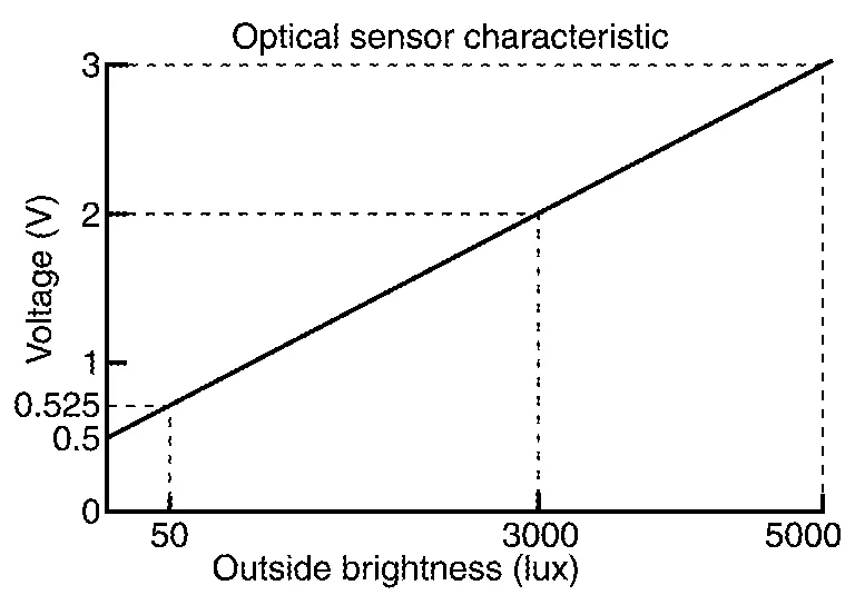
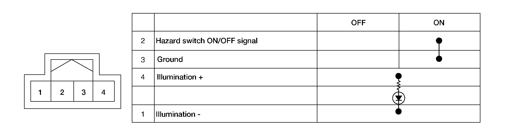
| 15. | Hazard switch | Refer to Hazard Switch. |
| 16. | Rear turn signal lamp LH (rear combination lamp LH) (RH similar) | Refer to Bulb Specifications. |
| 17. | Rear combination lamp LH/RH | Refer to Bulb Specifications. |
| 18. | License plate lamp LH/ RH | Refer to Bulb Specifications. |
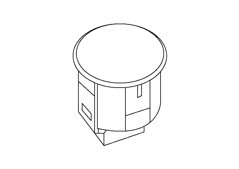
| 19. | Optical sensor | Refer to Optical Sensor. |
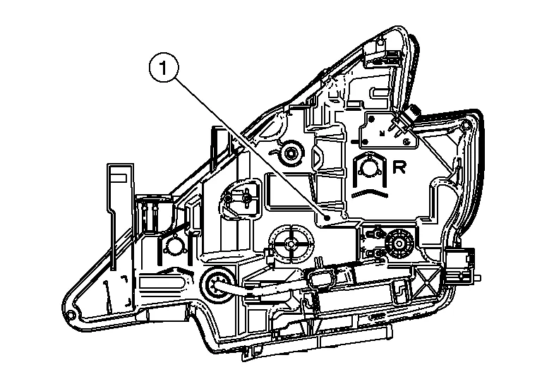
| 20. | LED headlamp control module | Refer to LED Headlamp Control Module. |
| 21. | TCM (Transmission Control Module) |
Controls back-up lamps ON/OFF when operated by CVT shift selector. Refer to TCM for detailed component location. |
| 22. | Transmission range switch |
Transmits transmission range switch signal to the TCM. Refer to Transmission range switch for detailed component location. |
-
The optical sensor is installed on the top of the instrument panel RH.
-
Optical sensor converts the outside brightness (lux) to voltage and transmits the optical sensor signal to BCM.
-
The hazard switch is installed in the center of the instrument panel.
-
Inputs the hazard switch ON/OFF signal to the BCM.
-
LED headlamp control module (1) is integrated into the front combination lamp.
-
Turns the LED headlamp ON according to the request from the IPDM E/R.

 System
..
Other information:
Nissan Murano (Z52) 2015-2024 Service Manual: Component Parts. Power Distribution System
Component Parts Location A. Front of center console B. Instrument lower panel LH No. Component Function 1. Push-button ignition switch Refer to Push-Button Ignition Switch. 2. IPDM E/R (Intelligent Power Distribution Module Engine Room) IPDM E/R detects the push-button ignition switch status, and transmits the push-button ignition switch status signal (CAN) to BCM...
Nissan Murano (Z52) 2015-2024 Service Manual: P0643 Sensor Power Supply
DTC Description DESCRIPTIONECM supplies a voltage of 5 V to some of the sensors systematically divided into 2 groups, respectively. Accordingly, when a short circuit develops in a sensor power source, a malfunction may occur simultaneously in the sensors belonging to the same group as the short-circuited sensor...
Categories
- Manuals Home
- Nissan Murano Owners Manual
- Nissan Murano Service Manual
- Warning lights
- Passenger compartment
- GAS STATION INFORMATION
- New on site
- Most important about car
Vehicle security system

Your vehicle has two types of security systems:
Vehicle security system NISSAN Vehicle Immobilizer SystemThe vehicle security system provides visual and audible alarm signals if someone opens the doors, liftgate or the hood when the system is armed. It is not, however, a motion detection type system that activates when a vehicle is moved or when a vibration occurs.