Nissan Murano: System Description / Component Parts. Driveline System
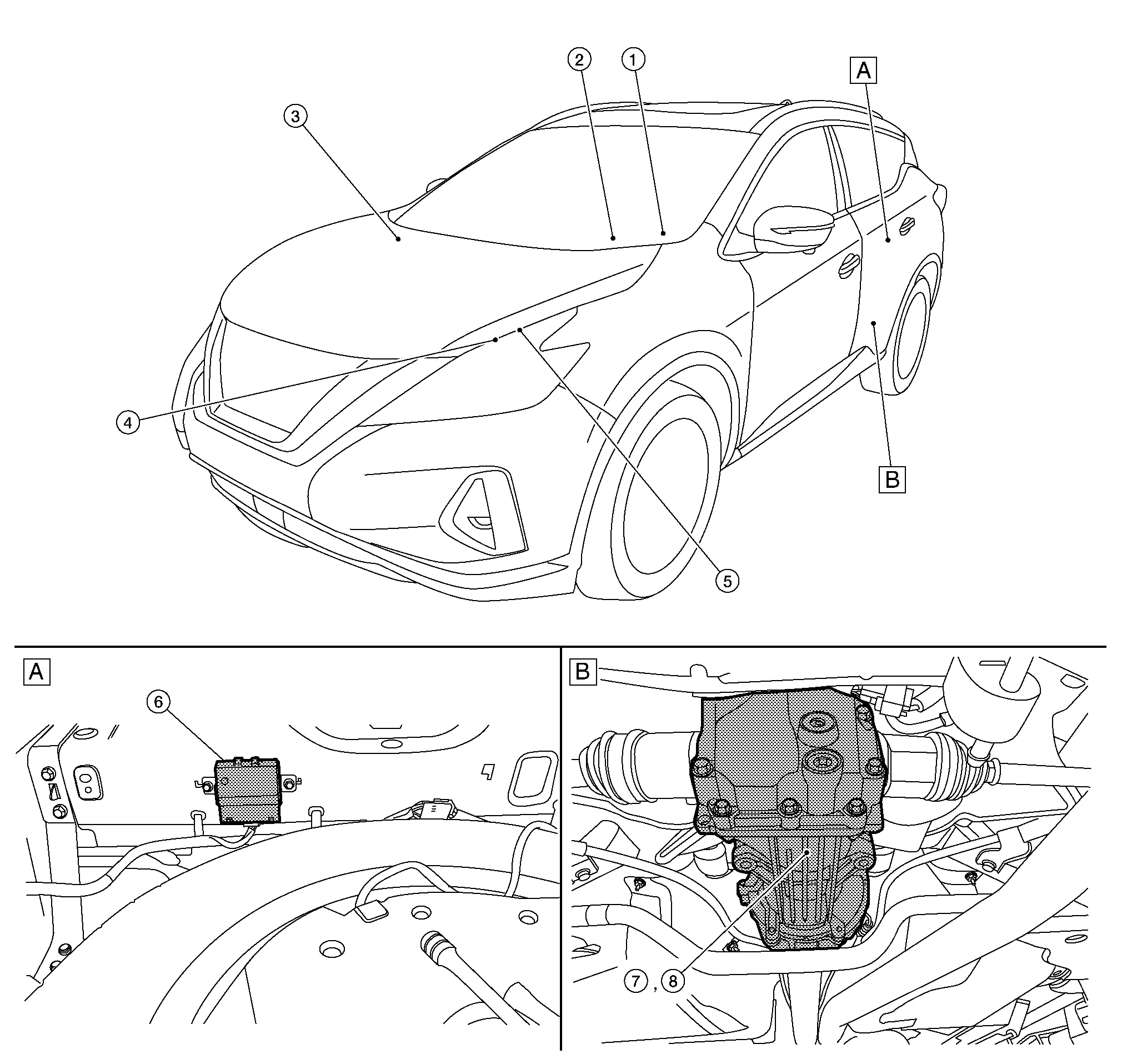
| A. | Inside storage room | B. | Rear final drive |
| No. | Component | Function |
|---|---|---|
| 1. | Steering angle sensor |
Mainly transmits the following signal to AWD control unit via CAN communication:
|
| 2. |
Combination meter [AWD (All-Wheel Drive) warning icon/display] |
Mainly transmits the following signal to AWD control unit via CAN communication:
Mainly receives the following signal from AWD control unit via CAN communication:
|
| 3. | ABS (Anti-lock Braking System) actuator and electric unit (control unit) |
Mainly transmits the following signals to AWD control unit via CAN communication:
|
| 4. | ECM (Engine Control Module) |
Mainly transmits the following signals to AWD control unit via CAN communication:
|
| 5. | TCM (Transmission Control Module) |
Mainly transmits the following signals to AWD control unit via CAN communication:
|
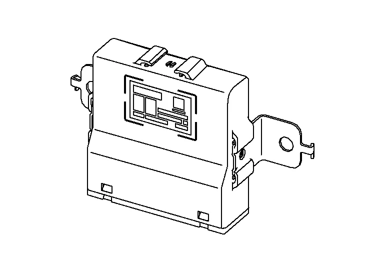
| 6. | AWD control unit | Refer to AWD Control Unit. |
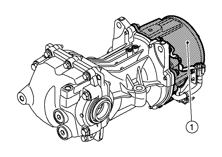
| 7. | Electric controlled coupling | Refer to Electric Controlled Coupling. |
| 8. | AWD solenoid | Refer to AWD Solenoid. |
-
The AWD control unit is located behind the back door kicking plate.
-
Controls driving force distribution by signals from each sensor from front wheel driving mode (100:0) to 4-wheel driving mode (50:50).
-
Front wheel driving conditions is available by fail-safe function if malfunction is detected in AWD system.
-
AWD actuator relay is integrated with AWD control unit, and supplies AWD solenoid with voltage.
Controls electric controlled coupling by command current from AWD control unit.
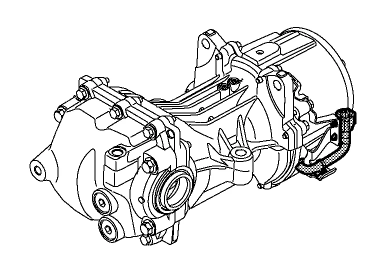
Electric controlled coupling (1) is integrated with rear final drive and transmits driving force to rear final drive. For operation, refer to Operation Description.
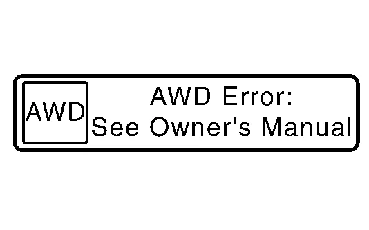
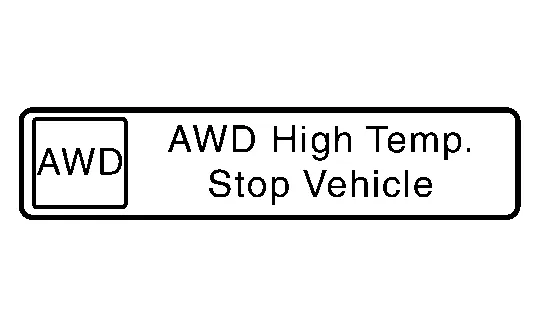
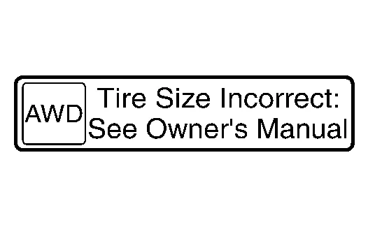
AWD warning icon/display is displayed when there is a malfunction in AWD system. AWD warning icon/display indicates the Nissan Murano vehicle is in fail-safe mode and shifting to front-wheel drive or 4-wheel drive (rear-wheels still have some driving torque).
AWD WARNING ICON/DISPLAY INDICATION
| Condition | AWD warning icon/display |
|---|---|
| AWD system malfunction |
|
|
Protection function is activated due to heavy load to electric controlled coupling. (AWD system is not malfunctioning and AWD system changes to front wheel drive.) When this message is displayed, refer to Description. |
|
|
Large difference in diameter of front/rear tires When this message is displayed, refer to Diagnosis Procedure. |
|
| Other than above (system normal) | OFF |
CAUTION:
-
AWD warning icon/display is displayed due to data reception error, CAN communication error etc.

 Structure and Operation
Sectional View
Transfer cover
Transfer case
Ring gear bearing (transfer case side)
Ring gear shaft
Pinion bearing
Drive pinion
Companion flange
Ring gear
Ring gear bearing (transfer cover side)
Operation Description
POWER TRANSFER DIAGRAMELECTRIC CONTROLLED COUPLING
The AWD control unit supplies command current to electric controlled coupling (AWD solenoid)...
Other information:
Nissan Murano (Z52) 2015-2024 Service Manual: B1360 Combination Meter
DTC Description DTC DETECTION LOGIC DTC No. CONSULT screen terms (Trouble diagnosis content) DTC detection condition B1360–02 Combination meter (Combination meter connection error) Diagnosis condition When ignition switch is ON. Signal (terminal) — Threshold — Diagnosis delay time — POSSIBLE CAUSE AV communication circuit is open Combination meter FAIL-SAFESteering switch is inoperative DTC Confirmation Procedure PERFORM DTC CONFIRMATION PROCEDURE CONSULT Ignition switch ON...
Nissan Murano (Z52) 2015-2024 Owners Manual: Installing the spare tire
The spare tire is designed for emergency use. For additional information, refer to “Wheels and tires” in the “Do-it-yourself” section of this manual. Clean any mud or dirt from the surface between the wheel and hub. Carefully put the spare tire on and tighten the wheel nuts finger tight...
Categories
- Manuals Home
- Nissan Murano Owners Manual
- Nissan Murano Service Manual
- System malfunction
- Indicator lights
- Jacking up vehicle and removing the damaged tire
- New on site
- Most important about car
Seatback pockets

Theremaybe one or two seatback pockets located on the back of the driver and passenger seats. The pockets can be used to store maps.
WARNING