Nissan Murano: Heater & Air Conditioning Control System :: System Description / Component Parts. Automatic Air Conditioning System
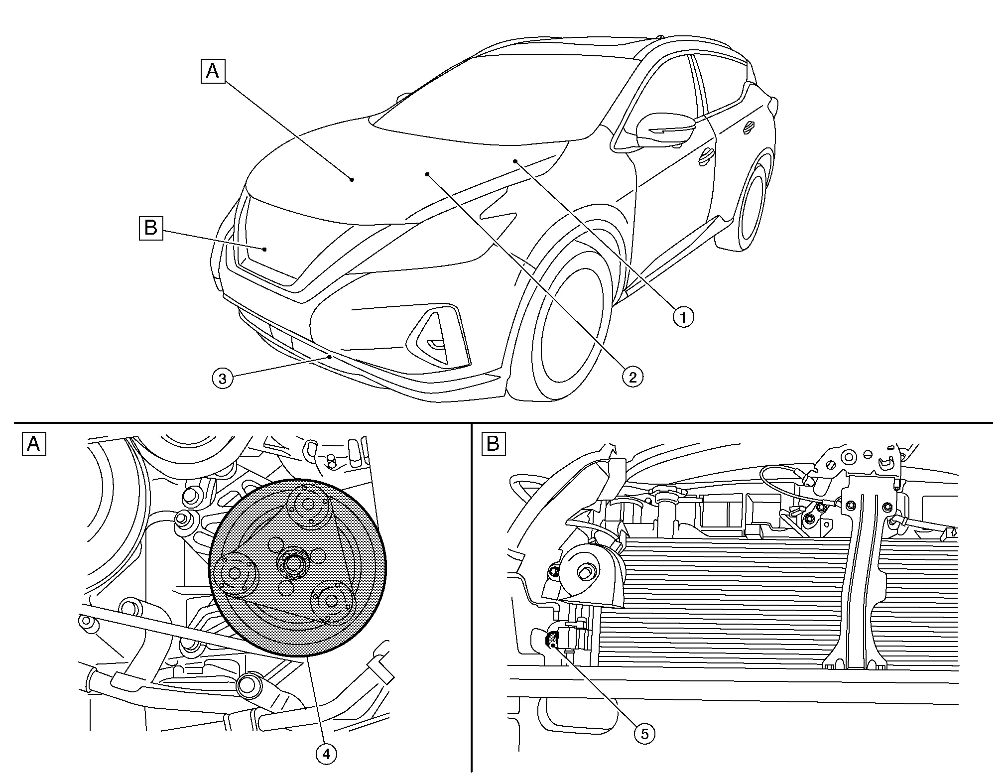
| A. | RH front of engine compartment | B. | View with front fascia removed from Nissan Murano vehicle |
| No. | Component | Function | |
|---|---|---|---|
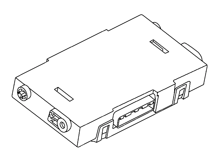
| 1. | IPDM E/R (Intelligent Power Distribution Module Engine Room) |
A/C relay is integrated in IPDM E/R. IPDM E/R operates A/C relay when A/C compressor request signal is received from ECM via CAN communication line. Refer to System Description. |
|
| 2. | ECM (Engine Control Module) |
The ECM sends a compressor ON request to the IPDM E/R based on the status of engine operation and load as well as refrigerant pressure information. If all the conditions are met for A/C operation, the ECM transmits the compressor ON request to the IPDM E/R. The ECM shares the refrigerant pressure sensor signal, engine RPM, and engine coolant temperature with the A/C auto amp. via CAN communication line. Refer to Component Parts Location for detailed component location. |
|
| 3. | Ambient sensor | Refer to Ambient Sensor. | |
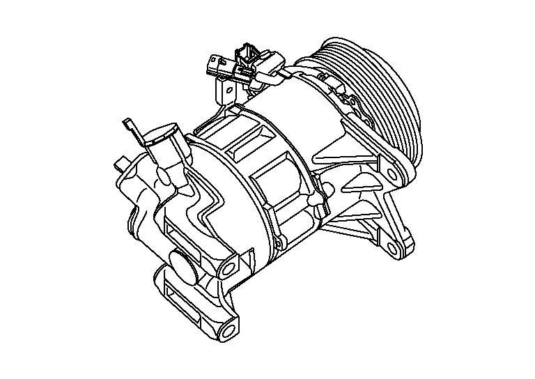
| 4. | A/C Compressor | Refer to A/C Compressor. | |
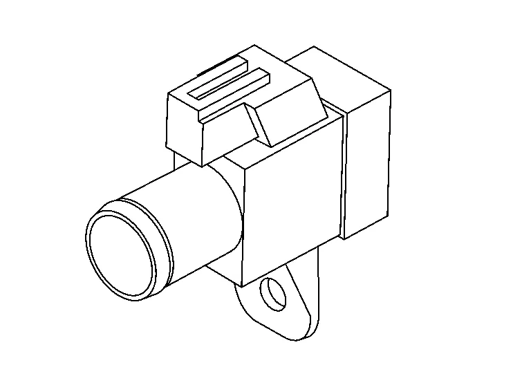
| 5. | Refrigerant pressure sensor | Refer to Refrigerant Pressure Sensor. | |
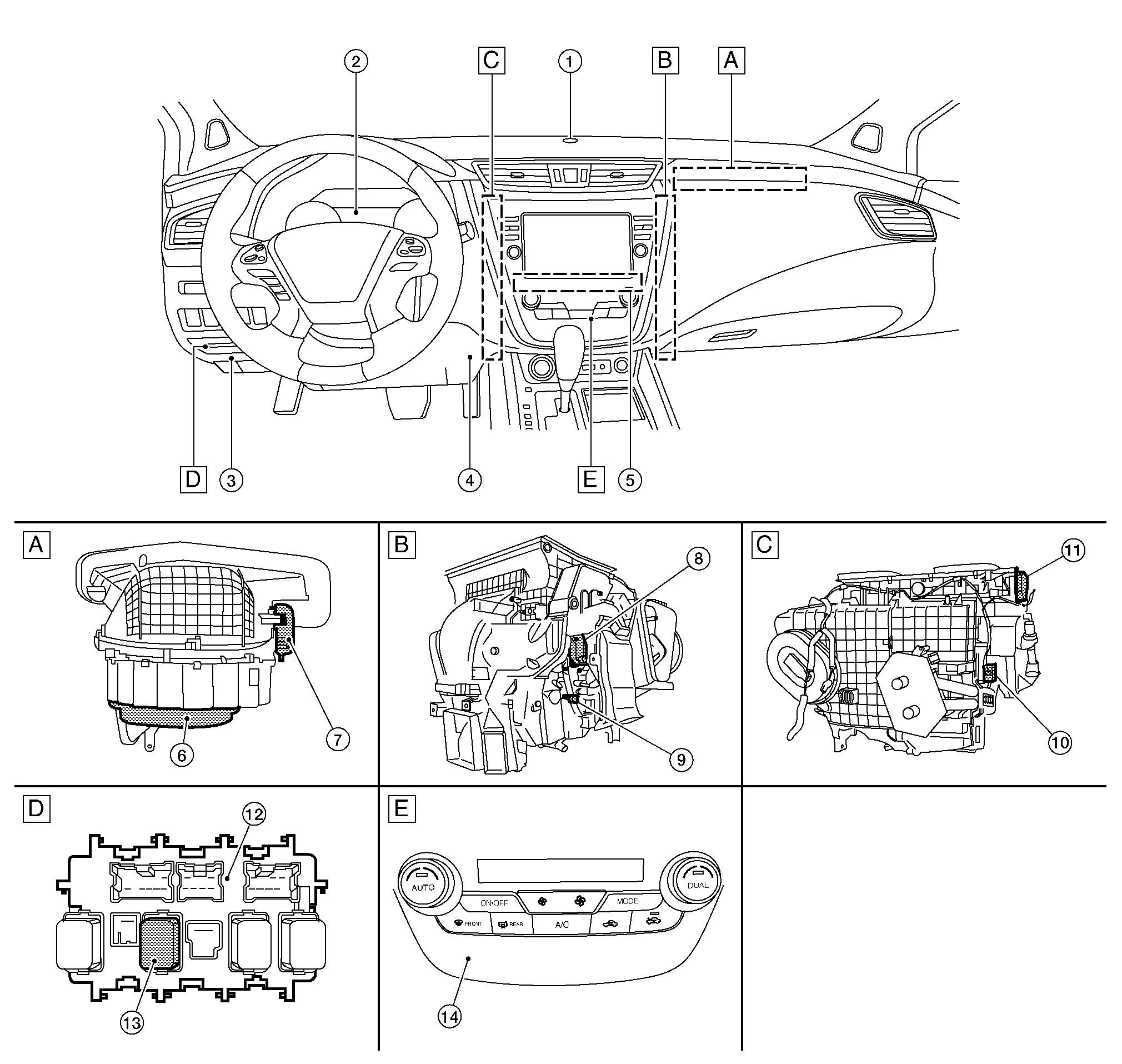
| A. | Behind RH side of instrument panel (view with front blower assembly removed from Nissan Murano vehicle) | B. | Behind RH center of instrument panel (view with A/C assembly removed from Nissan Murano vehicle) | C. | Behind LH center of instrument panel (view with A/C assembly removed from Nissan Murano vehicle) |
| D. | LH side of instrument panel | E. | Center of instrument panel | ||
| No. | Component | Function |
|---|---|---|
| 1. | Sunload sensor | Refer to Sunload Sensor. |
| 2. | BCM (Body Control Module) |
BCM transmits blower motor ON signal to the front and rear blower motor relays. Refer to System Description. |
| 3. | Accessory relay-2 | Refer to System Description. |
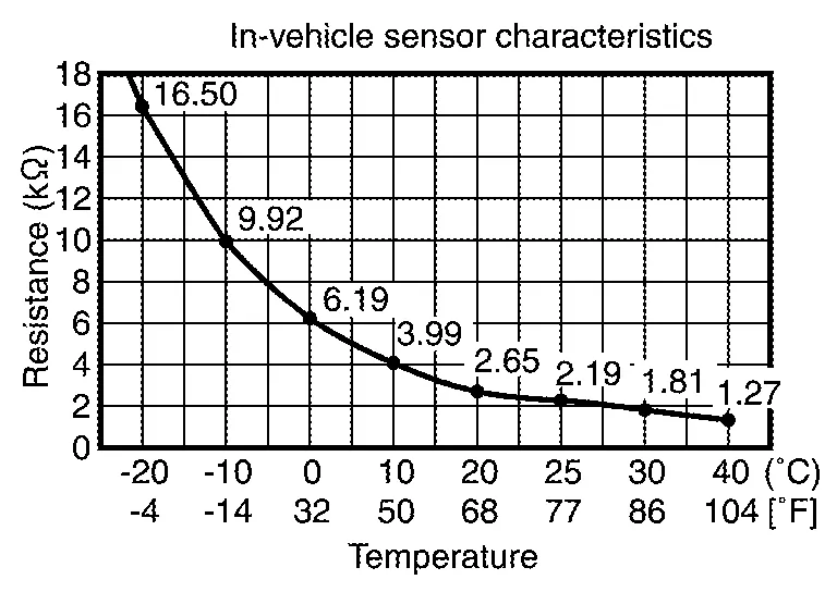
| 4. | In-Nissan Murano vehicle sensor | Refer to In-vehicle Sensor. |
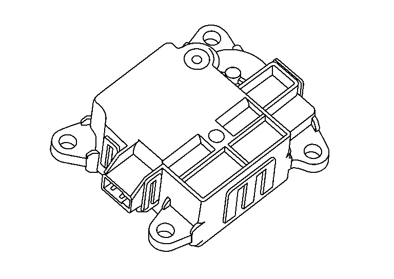
| 5. | A/C auto amp. | Refer to A/C Auto Amp.. |
| 6. | Front blower motor | Refer to Front Blower Motor. |
| 7. | Intake door motor | Refer to Intake Door Motor. |
| 8. | Air mix door motor RH | Refer to Air Mix Door Motor RH. |
| 9. | Intake sensor | Refer to Intake Sensor. |
| 10. | Air mix door motor LH | Refer to Air Mix Door Motor LH. |
| 11. | Mode door motor | Refer to Mode Door Motor. |
| 12. | Fuse block (J/B) | Located in the passenger compartment, behind the left lower IP, the fuse block (J/B) contains the front blower motor relay and several fuses required for the air conditioner control system. |
| 13. | Front blower motor relay | The front blower motor relay controls the flow of current to fuses 17 and 27 in the fuse block (J/B). The relay is connected directly to ground, and is controlled by the BCM. |
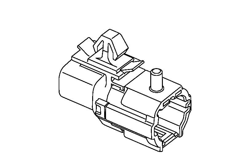
| 14. | A/C switch assembly |
A/C control operation signal is transmitted from the A/C switch assembly to the A/C auto amp. Refer to Switch Name and Function. |
-
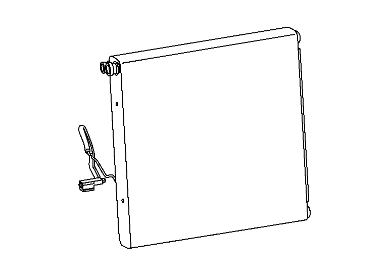
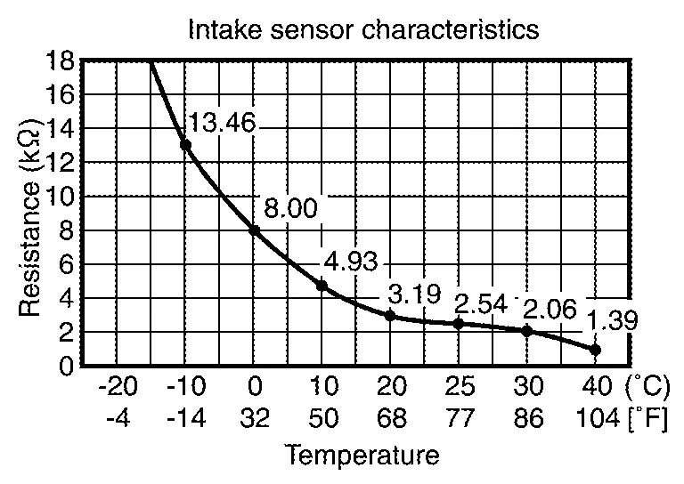
Intake sensor is located on the evaporator.
-
Intake sensor measures temperature of evaporator fin temperature. The sensor uses a thermistor which is sensitive to the change in temperature. The electrical resistance of the thermistor decreases as temperature increases.
-
Air mix door motor LH is installed on the A/C unit assembly.
-
Air mix door motor LH consists of motor that drives door, PBR (Potentio Balance Register) that detects door position and LCU (Local Control Unit) that perform multiplex communication control (LIN) with A/C auto amp. Refer to Door Control.
-
Rotation of motor is transmitted to air mix door LH by link and lever. Air flow temperature is switched.
-
Air mix door motor RH is installed on the A/C unit assembly.
-
Air mix door motor RH consists of motor that drives door, PBR (Potentio Balance Register) that detects door position and LCU (Local Control Unit) that perform multiplex communication control (LIN) with A/C auto amp. Refer to Door Control.
-
Rotation of motor is transmitted to air mix door RH by link and lever. Air flow temperature is switched.
-
Mode door motor is installed on the A/C unit assembly.
-
Mode door motor consists of motor that drives door, PBR (Potentio Balance Register) that detects door position and LCU (Local Control Unit) that perform multiplex communication control (LIN) with A/C auto amp. Refer to Door Control.
-
Rotation of motor is transmitted to mode door (ventilator door, foot door, and defroster door) by link and lever. Air outlet is switched.
-
Intake door motor is installed on the blower assembly.
-
Intake door motor consists of motor that drives door, PBR (Potentio Balance Register) that detects door position and LCU (Local Control Unit) that perform multiplex communication control (LIN) with A/C auto amp. Refer to Door Control.
-
Rotation of motor is transmitted to intake door by lever. Air inlet is switched.
-
Front blower motor is installed on the blower assembly.
-
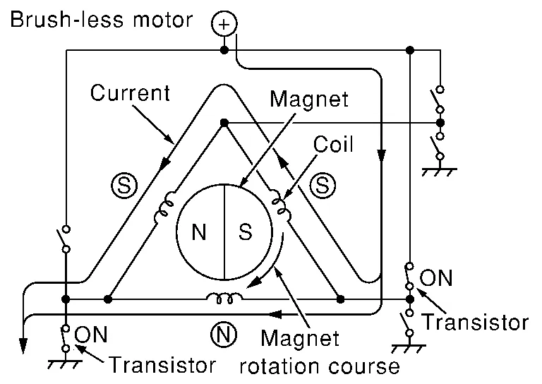
The blower motor utilizes a brush-less motor with a rotating magnet.
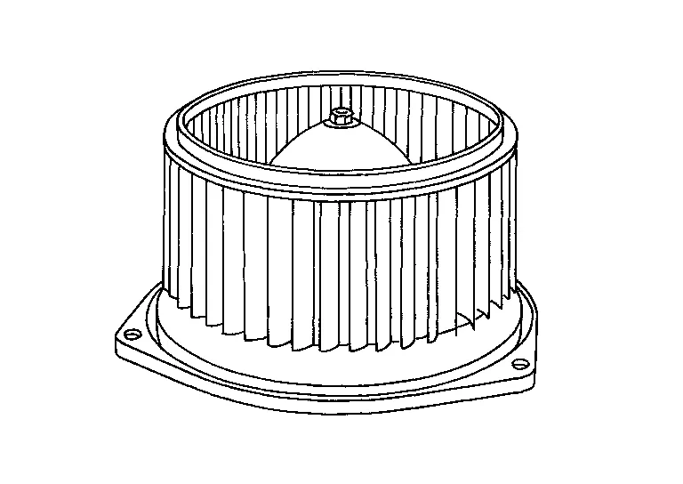
-
Quietness is improved over previous motors where the brush was the point of contact and the coil rotated.
-
A/C compressor is installed on RH side of the engine.
-
Vaporized refrigerant is drawn into the A/C compressor from the evaporator, where it is compressed to a high pressure, high temperature vapor. The hot compressed vapor is then discharged to the condenser.
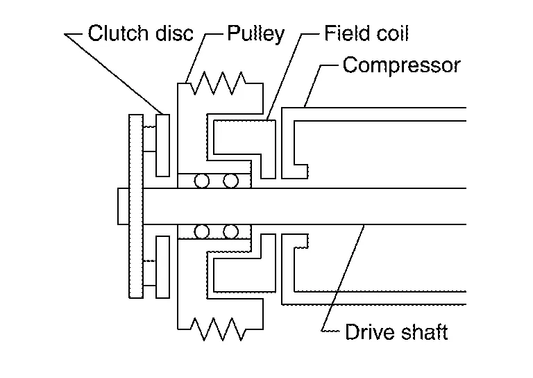
MAGNET CLUTCH
Description
A/C compressor is driven by the magnet clutch which is magnetized by electric power supply.
Structure and Operation
-
Magnet clutch consists of pulley, clutch disc, and field coil.
-
Pulley is connected with crankshaft pulley of engine via drive belt and is always rotated while engine is running.
-
Clutch disc is connected with drive shaft of A/C compressor.
-
Field coil, which becomes a strong electric magnet when electricity is supplied, strongly pulls clutch disc and presses it to pulley.
-
-
When A/C relay integrated in IPDM E/R turns ON, electricity is supplied to field coil, clutch disc is presses to pulley, and engine rotational movement is transmitted from crankshaft pulley ⇒ drive belt ⇒ pulley ⇒ clutch disc ⇒ drive shaft. A/C compressor is operated. When A/C relay turns OFF, electricity is not supplied to field coil, and clutch disc is released from pulley. A/C compressor is not operated.
ECV (ELECTRICAL CONTROL VALVE)
ECV (electrical control valve) is installed on the A/C compressor and controls emitting the appropriate amount of refrigerant when necessary.
-
A/C auto amp. is installed behind center of the instrument panel.
-
A/C auto amp. controls automatic air conditioning system by inputting and calculating signals from each sensor and each switch. A/C auto amp. has self-diagnosis function. Diagnosis of automatic air conditioning system can be performed quickly.
-
Ambient sensor is installed behind LH side of the front bumper.
-
Ambient sensor measures ambient air temperature. The sensor uses a thermistor which is sensitive to the change in temperature. The electrical resistance of the thermistor decreases as temperature increases.

-
In-vehicle sensor is installed on the instrument lower panel.
-
In-vehicle sensor measures temperature of intake air that flows through aspirator to passenger room. The sensor uses a thermistor which is sensitive to the change in temperature. The electrical resistance of the thermistor decreases as temperature increases.
-
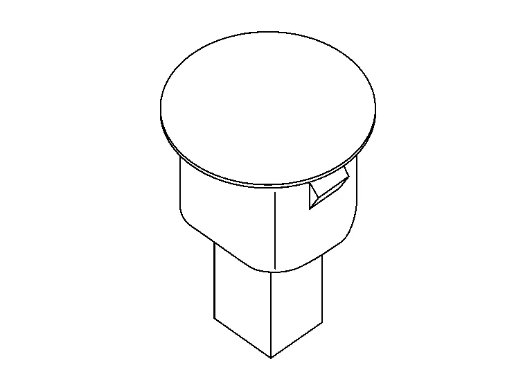
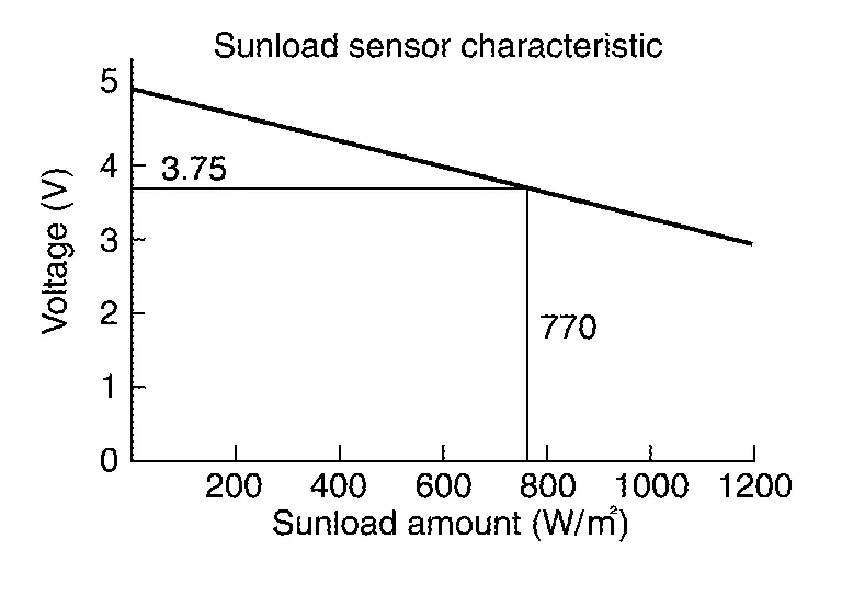
Sunload sensor is installed on center of the instrument panel.
-
Sunload sensor measures sunload amount. This sensor converts sunload amount to voltage signal by photodiode and transmits to A/C auto amp.
DESCRIPTION
-
Refrigerant pressure sensor is installed on the high pressure pipe.
-
The refrigerant pressure sensor converts high-pressure side refrigerant pressure into voltage and outputs it to ECM.
-
ECM operates cooling system protection and idle speed control according to voltage value that is input.
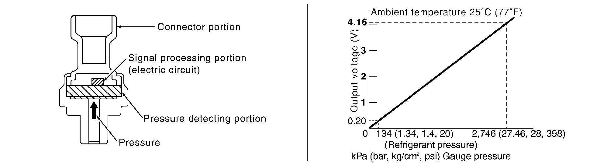
STRUCTURE AND OPERATION
-
The refrigerant pressure sensor is a capacitance type sensor. It consists of a pressure detection area and a signal processing area.
-
The pressure detection area, which is a variable capacity condenser, changes internal static capacitance according to pressure force.
-
The signal processing area detects the static capacitance of the pressure detection area, converts the static capacitance into a voltage value, and transmits the voltage value to ECM.

 System
System Description
SYSTEM DIAGRAMINPUT/OUTPUT SIGNAL Component Signal status
BCM
Receives blower motor ON signal from A/C auto amp. via CAN communication...
Other information:
Nissan Murano (Z52) 2015-2024 Service Manual: B2098 Ign Relay on Circ
DTC Description IPDM E/R operates the ignition relay-1 when it receives an ignition switch ON signal from BCM via CAN communication. Turn the ignition relay-1 OFF by pressing the push-button ignition switch once when the Nissan Murano vehicle speed is 2...
Nissan Murano (Z52) 2015-2024 Owners Manual: Two-Wheel Drive models with Continuously Variable Transmission (CVT)
NISSAN recommends that your vehicle be towed with the driving (front) wheels off the ground or place the vehicle on a flatbed truck as illustrated. CAUTION Never tow Continuously Variable Transmission (CVT) models with the front wheels on the ground or four wheels on the ground (forward or backward), as this may cause serious and expensive damage to the transmission...
Categories
- Manuals Home
- Nissan Murano Owners Manual
- Nissan Murano Service Manual
- How to enable/disable the LDW system
- Warning lights
- Vehicle Dynamic Control (VDC) OFF switch
- New on site
- Most important about car
Autolight system
The autolight system allows the headlights to turn on and off automatically. The autolight system can:
Turn on the headlights, front parking, tail, license plate and instrument panel lights automatically when it is dark. Turn off all the lights (except daylight running lights) when it is light. Keep all the lights on for a period of time after you place the ignition switch in the OFF position and all doors are closed.