Nissan Murano: Heater & Air Conditioning Control System :: System Description / System
SYSTEM DIAGRAM
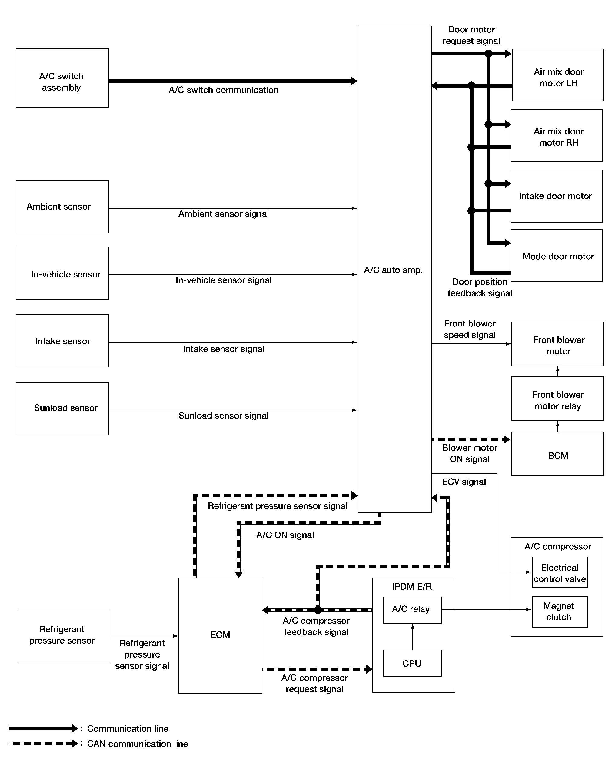
INPUT/OUTPUT SIGNAL
| Component | Signal status |
|---|---|
| BCM | Receives blower motor ON signal from A/C auto amp. via CAN communication. |
| ECM |
|
| IPDM E/R |
|
| Air mix door motor LH |
|
| Air mix door motor RH | |
| Mode door motor | |
| Intake door motor |
SYSTEM DESCRIPTION
-
Automatic air conditioning system is controlled by each function of A/C auto amp., ECM, IPDM E/R and BCM.
Control by A/C auto amp.
-
Air Flow Control
-
Air Inlet Control
-
Air Outlet Control
-
Compressor Control
-
Door Control
-
Temperature Control
-
Correction for input value of each sensor
Ambient sensor (setting temperature correction)
-
A/C auto amp. controls passenger room temperature so that the optimum level always matches the temperature level that the passenger may feel. Correction is applied to the target temperature that is set using temperature control dial, according to ambient temperature detected by ambient sensor.
In-Nissan Murano vehicle sensor [in-vehicle temperature (front side) correction]
-
Passenger room temperature (front side) detected by in-Nissan Murano vehicle sensor is corrected for each front air conditioning control (driver side and passenger side).
Intake sensor (intake temperature correction)
-
A/C auto amp. performs correction to change recognition intake temperature of A/C auto amp. quickly when difference is large between recognition intake temperature and intake temperature detected by intake temperature sensor. The correction is performed to change recognition intake temperature slowly when difference is small.
Sunload sensor (sunload amount correction)
-
Sunload amount detected by sunload sensor is corrected for each air conditioning control.
-
A/C auto amp. performs correction to change recognition sunload amount of A/C auto amp. slowly when sunload amount changes quickly, for example when entering or exiting a tunnel.
-
Control by ECM
-
Cooling fan control
Refer to System Description.
-
Air conditioning cut control
Refer to System Description.
Control by IPDM E/R
-
Relay control
Refer to System Description.
-
Cooling fan control
Refer to System Description.
Control by BCM
-
Relay control
Refer to System Description.
-
-
A/C switch assembly transmits the commands for automatic air conditioning system operation to A/C auto amp. via communication line. A/C auto amp. transmits each indication information to A/C switch assembly via communication line. A/C switch assembly displays each indication information that is received.
DESCRIPTION
-
A/C auto amp. changes duty ratio of front blower motor drive signal and controls air flow continuously. When air flow is increased, duty ratio of front blower motor control signal gradually increases to prevent a sudden increase in air flow.
-
In addition to manual control and automatic control, air flow control consists of starting fan speed control, low coolant temperature starting control, high in-Nissan Murano vehicle temperature starting control and fan speed control at door motor operation.
AUTOMATIC AIR FLOW CONTROL
-
A/C auto amp. decides target air flow depending on target air mix door (front) opening angle.
-
A/C auto amp. changes duty ratio of front blower motor control signal and controls the air flow continuously so that air flow matches the target air flow.
-
When air outlet is VENT or B/L, the minimum air flow is changed depending on sunload.

STARTING AIR FLOW CONTROL
-
When front blower motor is activated, A/C auto amp. gradually increases duty ratio of front blower motor control signal to prevent a sudden increase in discharge air flow.

-
It takes approximately 8 seconds for air flow to reach HI from LOW.
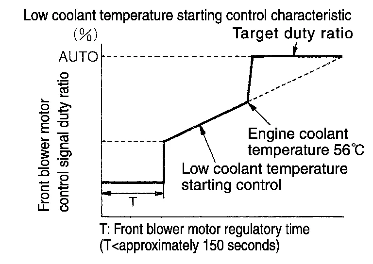
LOW COOLANT TEMPERATURE STARTING CONTROL
If the engine coolant temperature is 133°F (56°C) or less, to prevent a cold discharged air flow, A/C auto amp. suspends front blower motor activation for the maximum 150 seconds depending on target air mix door (front) opening angle. After this, front blower motor control signal is increased gradually, and front blower motor is activated.
HIGH IN-VEHICLE TEMPERATURE STARTING CONTROL
When front evaporator fin temperature is high [intake sensor value is 95°F (35°C) or more], to prevent a hot discharged air flow, A/C auto amp. suspends front blower motor activation for approximately 3 seconds so that front evaporator is cooled by refrigerant.
FAN SPEED CONTROL AT DOOR MOTOR OPERATION
When mode door motor is activated while air flow is more than the specified value, A/C auto amp. reduces fan speed temporarily so that mode door moves smoothly.
The intake door is automatically controlled by the temperature setting, ambient temperature, in-vehicle temperature, intake temperature, amount of sunload and ON/OFF operation of the A/C compressor.

Intake door automatic control selects FRE, 20% FRE, or REC depending on a target air mix door opening angle, based on in-Nissan Murano vehicle temperature, ambient temperature, and sunload.
-
While air outlet is in automatic control, A/C auto amp. selects the mode door position depending on a target air mix door angle and outlet air temperature calculated from sunload.

-
If ambient temperature is excessively low, D/F is selected to prevent windshield fogging when air outlet is set to FOOT.
DESCRIPTION
-
When the A/C compressor activation condition is satisfied while front blower motor is activated, A/C auto amp. transmits A/C ON signal and blower fan ON signal to ECM via CAN communication.
-
ECM judges that the A/C compressor can be activated depending on each sensors state (refrigerant pressure sensor signal and others) and transmits A/C compressor request signal to IPDM E/R via CAN communication.
-
IPDM E/R turns A/C relay ON and activates the A/C compressor depending on request from ECM.
COMPRESSOR PROTECTION CONTROL AT PRESSURE MALFUNCTION
When high-pressure side value that is detected by refrigerant pressure sensor is as per the following state, ECM requests IPDM E/R to turn A/C relay OFF and stops the A/C compressor.
-
3.12 MPa (31.82 kg/cm2, 452.4 psi) or more (When the engine speed is less than 1,500 rpm)
-
2.74 MPa (27.95 kg/cm2, 397.3 psi) or more (When the engine speed is 1,500 rpm or more)
-
0.14 MPa (1.43 kg/cm2, 20.3 psi) or less
COMPRESSOR OIL CIRCULATION CONTROL
When the engine starts while the engine coolant temperature is 133°F (56°C) or less, ECM activates the A/C compressor for approximately 6 seconds and circulates the A/C compressor lubricant once.
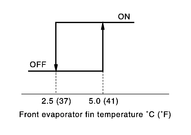
LOW TEMPERATURE PROTECTION CONTROL
-
When intake sensor detects that front evaporator fin temperature is 37°F (2.5°C) or less, A/C auto amp. requests ECM to turn A/C compressor OFF, and stops the A/C compressor.
-
When the front evaporator fin temperature returns to 41°F (5.0°C) or more, the A/C compressor is activated.
OPERATING RATE CONTROL
When set temperature is other than fully cold or air outlet is “VENT”, “B/L” or “FOOT”, A/C auto amp. controls the A/C compressor activation depending on ambient temperature.
AIR CONDITIONING CUT CONTROL
When engine is running in excessively high load condition, ECM requests IPDM E/R to turn A/C relay OFF, and stops the A/C compressor. Refer to System Description for details.
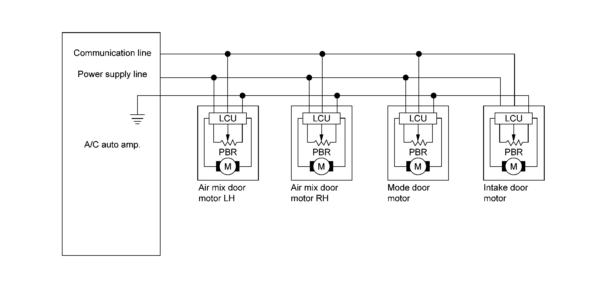
DOOR MOTOR CONTROL
-
LCU (Local Control Unit) is built into each door motor, and detects door position by PBR (Potentio Balance Resistor).
-
A/C auto amp. communicates with each LCU via communication line and receives each door position feedback signal from each LCU.
-
Each LCU controls each door to the appropriate position depending on the control signal from A/C auto amp.
-
Each LCU transmits the signal of door movement completion to A/C auto amp., when the door movement is completed.
SWITCH AND THEIR CONTROL FUNCTION
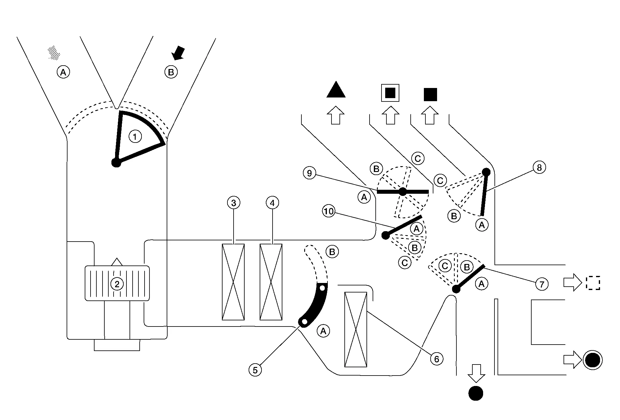
| 1. | Intake door | 2. | Front blower motor | 3. | In-cabin microfilter |
| 4. | Front evaporator | 5. | Air mix door (front) | 6. | Front heater core |
| 7. | Foot door | 8. | Ventilator door | 9. | Defroster door |
| 10. | Max. cool door | ||||
 |
Fresh air |  |
Recirculation air | Discharge air | |
 |
Defroster |  |
Center ventilator |  |
Side ventilator |
 |
Front foot |  |
Rear foot |  |
Rear ventilator |
| Switch position | Door position | |||||||||
|---|---|---|---|---|---|---|---|---|---|---|
| Mode door | Intake door | Air mix door | ||||||||
| Ventilator door | Max. cool door | Defroster door | Foot door | Driver side | Passenger side | |||||
| AUTO switch | .webp) |
AUTO | ||||||||
| MODE switch |  |
A | A | A | A | — | — | — | ||
 |
B | B | A | B | ||||||
 |
C | C | B | B | ||||||
 |
C | B | B | B | ||||||
| DEF switch |  |
|
C | A | C | C | ||||
| Intake switch* |  |
|
— | — | — | — | A | |||
 |
B | |||||||||
| Temperature control (Driver side) |
DUAL switch: OFF |
Full cold [60°F or 61°F (18°C)] |
— | A | ||||||
|
62°F – 88 °F (18.5°C – 31.5°C) |
AUTO | |||||||||
|
Full hot [89°F or 90°F (32°C)] |
B | |||||||||
| Temperature control (Driver side) | DUAL switch: ON |
Full cold [60°F or 61°F (18°C)] |
A | — | ||||||
|
62°F – 88 °F (18.5°C – 31.5°C) |
AUTO | |||||||||
|
Full hot [89°F or 90°F (32°C)] |
B | |||||||||
| Temperature control (Passenger side) |
Full cold [60°F or 61°F (18°C)] |
— | A | |||||||
|
62°F – 88 °F (18.5°C – 31.5°C) |
AUTO | |||||||||
|
Full hot [89°F or 90°F (32°C)] |
B | |||||||||
| ON·OFF switch | OFF | C | C | B | B | A | — | |||
*: Inlet status is displayed by indicator during activation of automatic control
AIR DISTRIBUTION
| Discharge air flow | |||||||
|---|---|---|---|---|---|---|---|
| MODE/DEF set position | Condition | Air outlet/distribution | |||||
| Ventilator | Foot | Defroster | |||||
| Center | Side | Rear | Front | Rear | |||
|
DUAL switch: OFF | 44% | 44% | 12% | — | — | |
|
22% | 22% | 17% | 29% | 10% | — | |
|
— | 10% | 17% | 36% | 14% | 23% | |
|
— | 10% | 17% | 28% | 13% | 32% | |
|
— | 10% | 14% | — | 76% | ||
-
When ignition switch is in the ON position, A/C auto amp. always automatically controls temperature regardless of front air conditioning operational state.
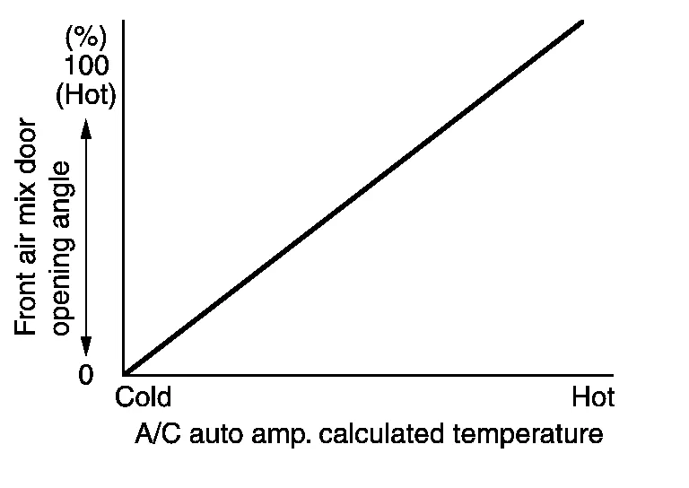
-
A/C auto amp. calculates the target air mix door opening angle depending on set temperature, in-Nissan Murano vehicle temperature, ambient temperature, and sunload.
-
Air mix door is controlled depending on the comparison of current air mix door opening angle and target air mix door opening angle.
-
Regardless of in-Nissan Murano vehicle temperature, ambient temperature, and sunload, air mix door is fixed at the fully cold position when set temperature is 60°F or 61°F (18°C), and at the fully hot position when set temperature is 89°F or 90°F (32.0°C).
 Component Parts. Automatic Air Conditioning System
Component Parts Location
A.
RH front of engine compartment
B.
View with front fascia removed from Nissan Murano vehicle
No. Component Function
1...
 Operation
Switch Name and Function
Controller (A/C switch assembly) 1.
AUTO switch
2.
Temperature control dial (driver side)
3.
Defroster switch
4.
Fan switch
5...
Other information:
Nissan Murano (Z52) 2015-2024 Service Manual: Bcm (body Control Module)
L..
Nissan Murano (Z52) 2015-2024 Owners Manual: Remote starting the vehicle
To use the Remote Engine Start feature perform the following: Aim the Intelligent Key at the vehicle. Press the button to lock all doors. Within 5 seconds press and hold the button until the turn signal lights flash and the tail lamps turn on...
Categories
- Manuals Home
- Nissan Murano Owners Manual
- Nissan Murano Service Manual
- Tire rotation
- Passenger compartment
- Fuel recommendation
- New on site
- Most important about car
Unfastening the seat belts. Checking seat belt operation
Unfastening the seat belts

To unfasten the seat belt, press the button
on the buckle  . The seat belt
automatically
retracts.
. The seat belt
automatically
retracts.