Nissan Murano: Engine Mechanical :: Removal and Installation / Intake Manifold Collector
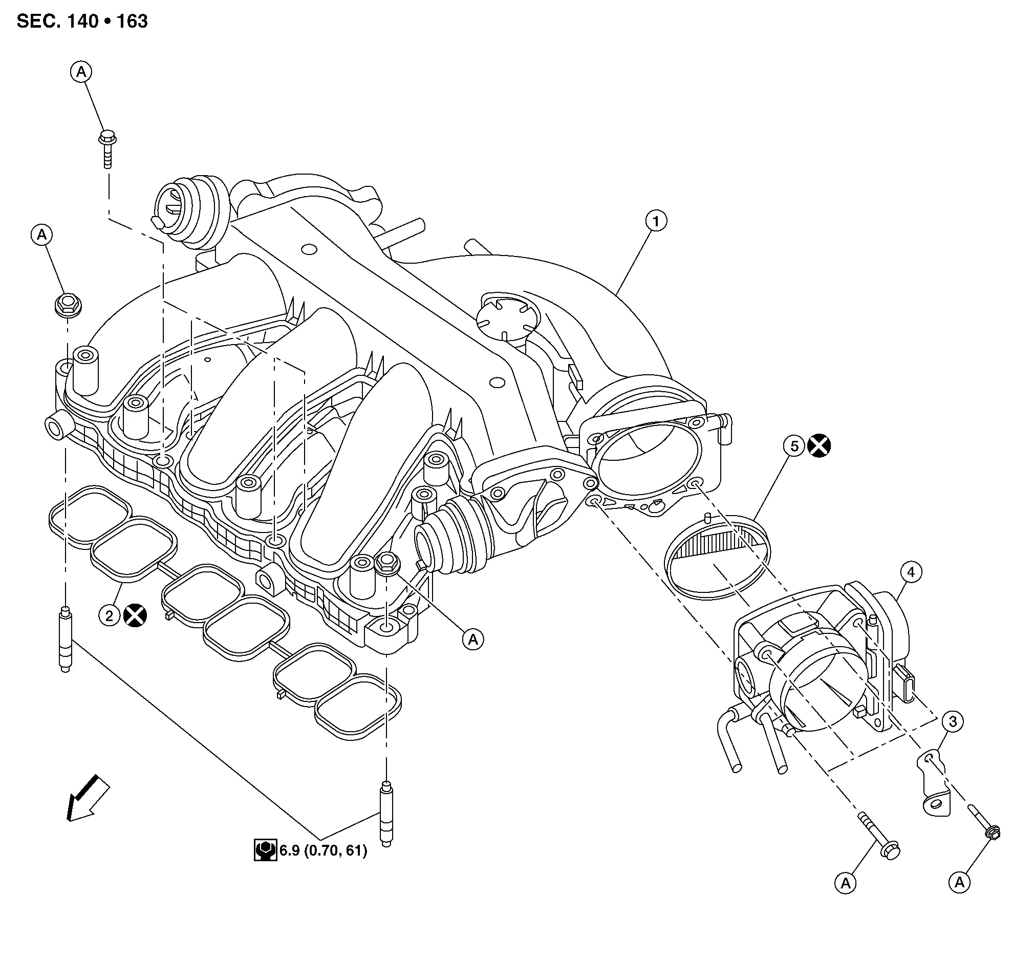
| 1. | Intake manifold collector | 2. | Intake manifold collector gasket | 3. | Bracket clip |
| 4. | Electric throttle control actuator | 5. | Electric throttle control actuator gasket | A. | Refer to Removal and Installation. |
| Front |
WARNING:
Do not drain the engine coolant when the engine is hot to avoid the danger of being scalded.
CAUTION:
-
Do not remove the power valves.
-
Cover engine openings to avoid the entry of any foreign material.
 NOTE:
NOTE:
When removing components such as hoses, tubes/lines, etc., cap or plug openings to prevent fluid from spilling.
REMOVAL
Remove the cowl top extension. Refer to Removal and Installation.
Remove the engine room cover. Refer to Removal and Installation.
Remove the air cleaner case (upper), air cleaner case (lower), and air duct and resonator assembly. Refer to Removal and Installation.
Disconnect the power brake booster vacuum hose.
Remove the vacuum hoses from the engine mount control valve solenoid.
Remove the vacuum hoses from the vacuum tube (front). Refer to Exploded View (FWD or Exploded View (AWD).
Disconnect the harness connector from VIAS control solenoid valve.
Disconnect the PCV hose.
Remove the air fuel ratio sensor 1 (bank 1) harness from the intake manifold collector.
Disconnect the harness connector from electric throttle control actuator.
Disconnect the EVAP canister purge volume control solenoid valve hose.
Remove the electric throttle control actuator bolts and remove the electric throttle control actuator and position aside. Loosening bolts in the reverse order as shown.

CAUTION:
-
Handle carefully to avoid any shock to the electric throttle control actuator.
-
Do not disassemble electric throttle control actuator.
Remove the VIAS control solenoid valve as necessary.
Remove the EVAP canister purge volume control solenoid valve.
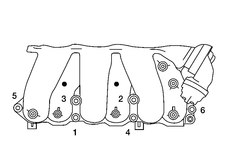
Loosen the intake manifold collector bolts and nuts, and remove the intake manifold collector and gasket. Loosening bolts and nuts in the reverse order as shown.
INSTALLATION
Installation is in the reverse order of removal.
-
Tighten intake manifold collector bolts and nuts in the order as shown.
Intake manifold collector bolts and nuts : 11.0 N·m (1.1 kg-m, 8 ft-lb) CAUTION:
Do not reuse intake manifold collector gasket.
-
Tighten electric throttle control actuator bolts in the order shown.
Electric throttle control actuator bolts : 8.4 N·m (0.86 kg-m, 74 in-lb) CAUTION:
Do not reuse electric throttle control actuator gasket.
NOTE:
After installation, re-calibrate the electric throttle control actuator as follows:
-
Perform the ″Throttle Valve Closed Position Learning″ when harness connector of the electric throttle control actuator is disconnected. Refer to Description.
-
Perform the ″Idle Air Volume Learning″ when the electric throttle control actuator is replaced. Refer to Description.
-
Perform the ″Accelerator Pedal Released Position Learning″ when the electric throttle control actuator is replaced. Refer to Description.
 Air Cleaner and Air Duct
Exploded View
1.
Air duct hose and resonator assembly
2.
Front air duct
3.
Grommet
4.
Air cleaner case (lower)
5.
Grommets
6.
Air cleaner case mounting bracket
7...
 Intake Manifold
Exploded View
1.
Intake manifold
2.
Intake manifold gasket
A.
Refer to Removal and Installation.
Removal and Installation
REMOVALWARNING:
To avoid the danger of being scalded, do not drain the coolant when the engine is hot...
Other information:
Nissan Murano (Z52) 2015-2024 Owners Manual: Child safety
WARNING Do not allow children to play with the seat belts. Most seating positions are equipped with Automatic Locking Retractor (ALR) mode seat belts. If the seat belt becomes wrapped around a child’s neck with the ALR mode activated, the child can be seriously injured or killed if the seat belt retracts and becomes tight...
Nissan Murano (Z52) 2015-2024 Service Manual: Warning Chime System :: Basic Inspection. Diagnosis and Repair Workflow
Work Flow OVERALL SEQUENCEDETAILED FLOWOBTAIN INFORMATION ABOUT SYMPTOM Interview the customer to obtain as much information as possible about the conditions and environment under which the malfunction occurred. >> GO TO 2. CHECK SYMPTOM Check the symptom based on the information obtained from the customer...
Categories
- Manuals Home
- Nissan Murano Owners Manual
- Nissan Murano Service Manual
- GAS STATION INFORMATION
- Warning lights
- High Beam Assist (if so equipped)
- New on site
- Most important about car
Driver and passenger supplemental knee air bag

Driver’s side
The knee air bag is located in the knee bolster, on the driver’s and passenger’s side. All of the information, cautions and warnings in this manual apply and must be followed. The knee air bag is designed to inflate in higher severity frontal collisions, although it may inflate if the forces in another type of collision are similar to those of a higher severity frontal impact. It may not inflate in certain collisions.

Passenger’s side