Nissan Murano: Basic Inspection / Calibrating Camera Image (intelligent Around View Monitor)
-
Calibration must be performed after removing/replacing the cameras, removing parts (e.g. front grille, door mirror, and others) mounted on the cameras, or replacing the Around view monitor control unit.
-
The use of CONSULT is required to perform calibration or writing of calibration results to the Around view monitor control unit.
-
Align the white lines on the road near the Nissan Murano vehicle at the boundary of each camera image by this camera calibration. The white lines far from the vehicle may not be aligned at the boundary of each camera image. The farther the line, the greater the difference is.
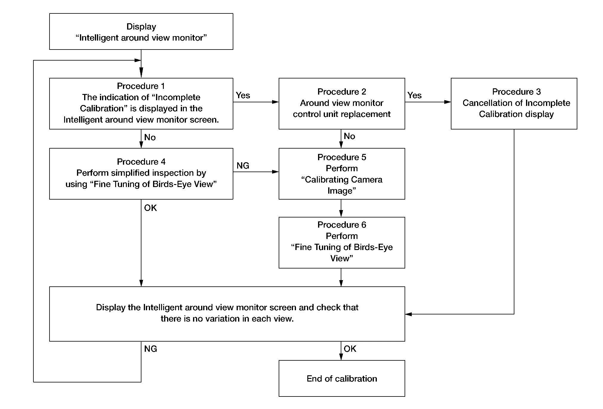
CALIBRATION FLOWCHART
Following the flowchart shown in the figure, perform the calibration.
 NOTE:
NOTE:
View in the incomplete calibration state is indicated by “ ” on the Intelligent around view monitor.
CALIBRATION PROCEDURE
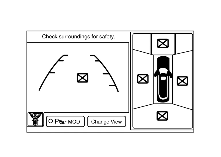
INTELLIGENT AROUND VIEW MONITOR SCREEN CONFIRMATION
Check that there is no indication of “Incomplete calibration”.
Is the “Incomplete calibration” display visible?
YES>>GO TO 2.
NO>>GO TO 4.
CHECK THAT AROUND VIEW MONITOR CONTROL UNIT IS REPLACED
Check that the around view monitor control unit is replaced.
Is the around view monitor control unit replaced?
YES>>GO TO 3.
NO>>GO TO 5.
CANCEL THE INDICATION OF INCOMPLETE CALIBRATION (PERFORM THIS ONLY AFTER REPLACING AROUND VIEW MONITOR CONTROL UNIT.)
 CONSULT
-
On the CONSULT screen, touch “CALIBRATING CAMERA IMAGE (FRONT CAMERA)”, “CALIBRATING CAMERA IMAGE (PASS-SIDE CAMERA)”, “CALIBRATING CAMERA IMAGE (DR-SIDE CAMERA)”, or “CALIBRATING CAMERA IMAGE (REAR CAMERA)” to accept the selection.
NOTE:
To cancel the indication of Incomplete calibration, select items based on the target camera.
-
On the adjustment screen of each camera, touch “APPLY” button. After this, touch “OK” button.
CAUTION:
-
Never perform operations other than those mentioned above.
-
Never perform “Initialize Camera Image Calibration”.
-
-
Display the Intelligent around view monitor screen to check that there is no errors, such as deviations among the camera images.
Is there a malfunction?
YES>>Calibration End.
NO>>GO TO 1.
PERFORM SIMPLIFIED CONFIRMATION/ADJUSTMENT BY “FINE TUNING OF BIRDS-EYE VIEW”
-
Put target line 1 on the ground beside each axle using packing tape, etc.
-
Put target lines 2 equal to the Nissan Murano vehicle total length + approximately 1.0 m (39.3 in) from the vehicle side (right and left) at approximately 30 cm (11.8 in) away from the Nissan Murano vehicle (make the line as parallel with the vehicle as possible).
Preparation of simplified target line
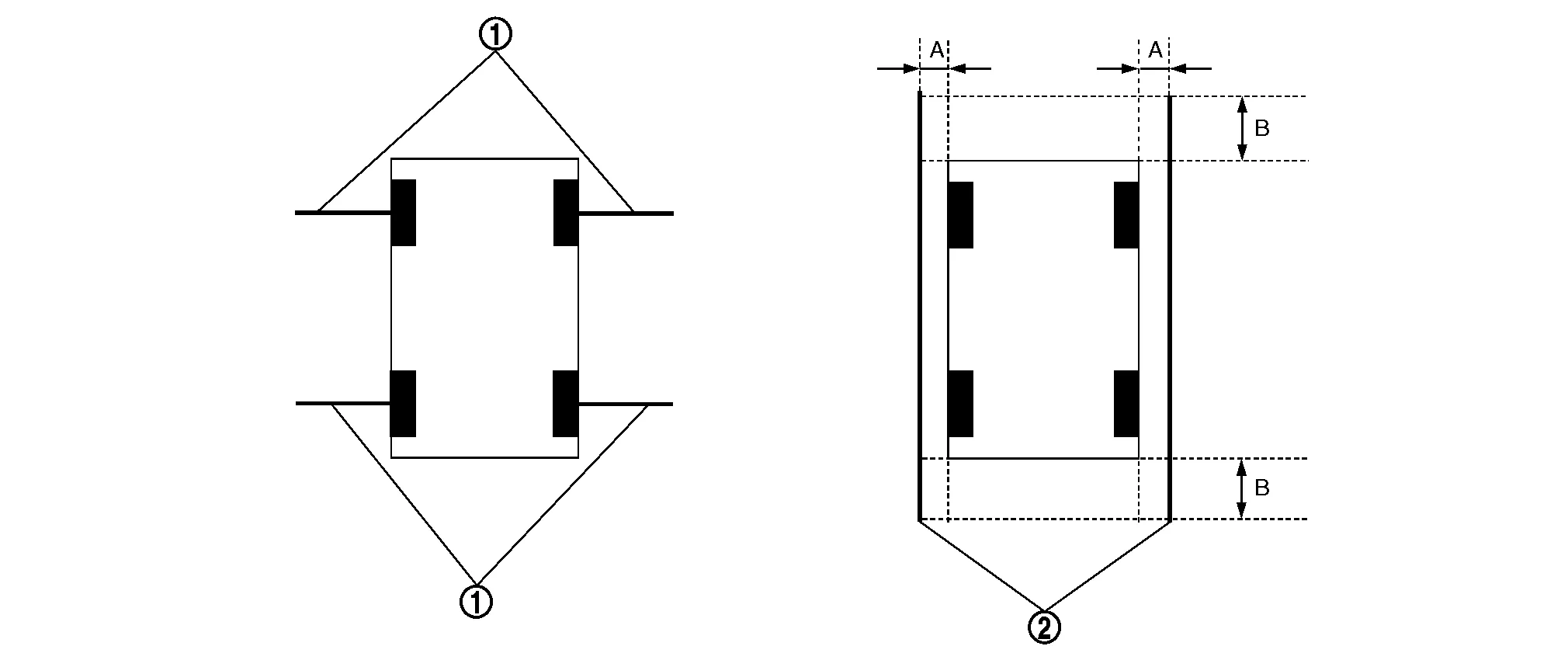
1. Target lines 1 2. Target lines 2 A. Approx. 30 cm (11.8 in) B. Approx. 1.0 m (39.3 in) -
CONSULT
Touch “FINE TUNING OF BIRDS-EYE VIEW” on the CONSULT screen.
-
On the CONSULT screen, touch “SELECT” button to select right or left camera and perform camera calibration as instructed below:
-
If the marker on the screen deviates from Target line 1, touch “AXIS X” button and “AXIS Y” button to adjust so that the marker is placed on the Target line 1.
-
If Target line 2 is misaligned among the cameras, adjust each camera image to bring Target line 2 into a straight line.
CAUTION:
Never adjust the front camera and rear camera. Only adjust the right and left cameras.
Simplified target line adjustment method
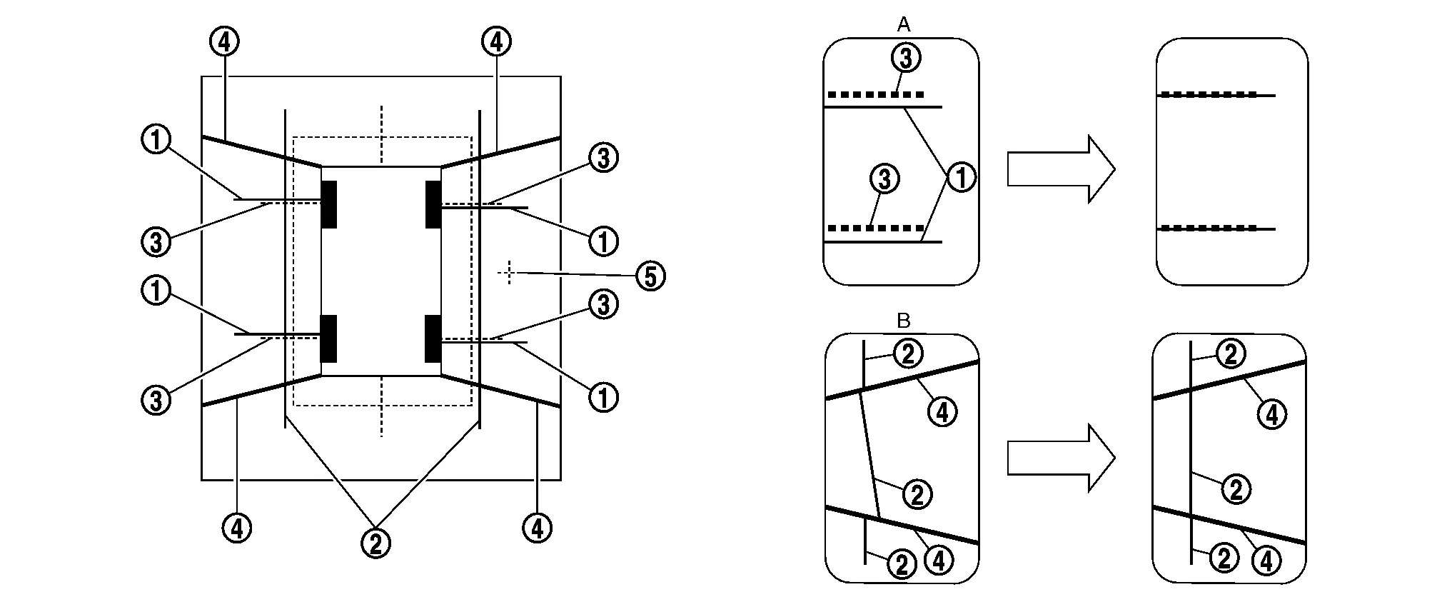
1. Target lines 1 2. Target lines 2 3. Marker for target line 1 4. Boundary between cameras 5. Crosshairs cursor (mark indicated the selected camera) A. Adjustment method for target lines 1 (right) B. Adjustment method for target lines 2 (right)
-
-
Adjust right and left cameras. Touch "APPLY" on the CONSULT screen to display adjustment results.
-
After adjusting right and left cameras, check that the marker is properly placed on the screen and there is no deviation in Target line 1.
NOTE:
-
It can be initialized to the NISSAN factory default condition with “Initialize Camera Image Calibration”.
-
The adjustment value is cancelled on this mode by performing “Initialize Camera Image Calibration”.
-
Is the difference corrected?
YES>>On the CONSULT screen, touch “OK” button to complete writing to the around view monitor control unit.
NO>>GO TO 5.
PERFORM “CALIBRATING CAMERA IMAGE”
Preparation of target line
-
Hang a string with a weight as shown in the figure. Put the points FM0, RM0 (mark) on the ground at the center of the Nissan Murano vehicle front end and rear end with white packing tape or a pen.
-
Route the vinyl string under the Nissan Murano vehicle, and then pull and fix it on the point approximately 1.0 m (39.9 in) to the front and rear of the vehicle through the points FM0 and RM0 using packing tape.
Target line preparation procedure 1
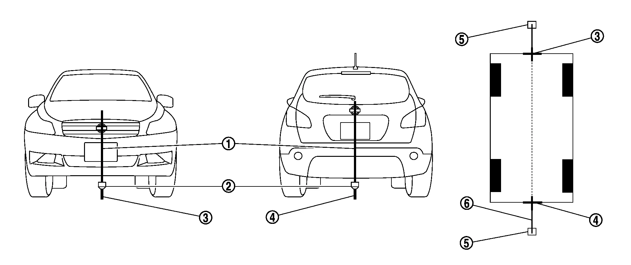
1. Thread 2. Weight 3. Point FM0 (mark) 4. Point RM0 (mark) 5. Packing tape (to fix the vinyl string) 6. Vinyl string -
Put the points FM and RM (mark) 75 cm (29.5 in) from the points FM0 and RM0 individually.
-
Route the vinyl string through the points FM and RM using a triangle scale, and then fix it at approximately 1.5 m (59 in) on both sides with packing tape.
-
Put the points FL, FR, RL, and RR (mark) to both right and left [Nissan Murano vehicle width / 2 + 30 cm (11.8 in)] from the points FM and RM.
Target line preparation procedure 2
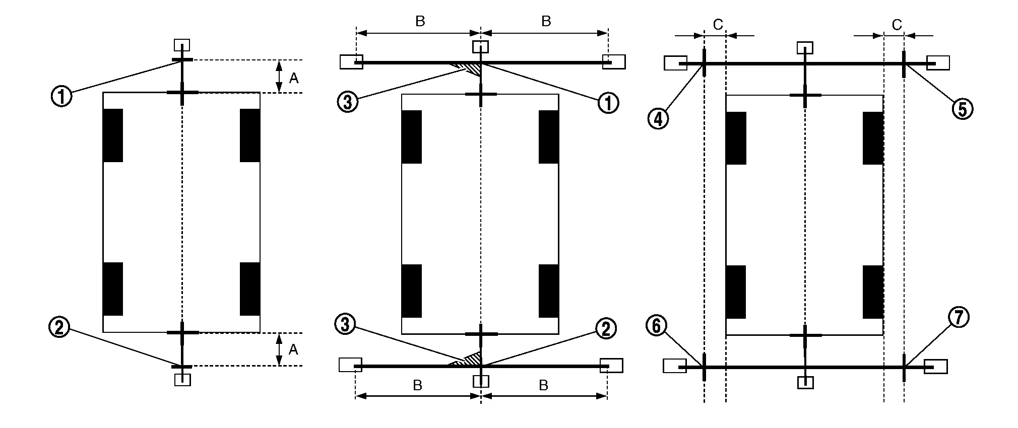
1. Point FM 2. Point RM 3. Triangle scale 4. Point FL (mark) 5. Point FR (mark) 6. Point RL (mark) 7. Point RR (mark) A. 75 cm (29.5 in) B. Approx. 1.5 m (59 in) C. 30 cm (11.8 in)
[Nissan Murano Vehicle width/ 2 + 30 cm (11.8 in) from the points FM and RM] -
Draw the lines of the points FL – RL and FR – RR with vinyl string, and fix it with packing tape.
-
Put a mark on the center of each axle, draw vertical lines to the lines of the points FL – RL and FR – RR from the marks on the center of the axle using a triangle scale, and then fix the lines using packing tape.
Target line preparation procedure 3
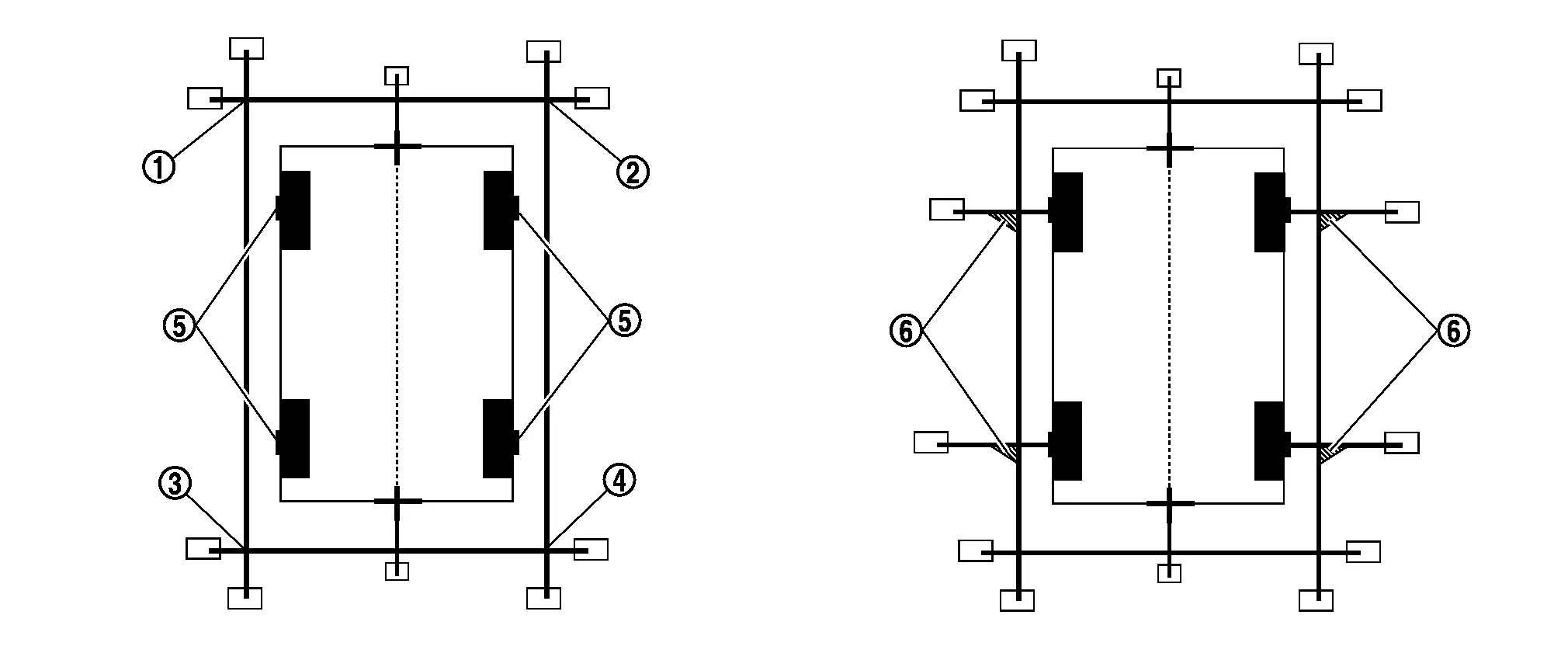
1. Point FL 2. Point FR 3. Point RL 4. Point RR 5. Center position of axle 6. Triangle scale
Perform “Calibrating Camera Image”
CONSULT
-
On the CONSULT screen, touch “CALIBRATING CAMERA IMAGE (FRONT CAMERA)”, “CALIBRATING CAMERA IMAGE (PASS-SIDE CAMERA)”, “CALIBRATING CAMERA IMAGE (DR-SIDE CAMERA)”, or “CALIBRATING CAMERA IMAGE (REAR CAMERA)” to accept the selection.
NOTE:
To cancel the indication of Incomplete calibration, select items based on the target camera.
-
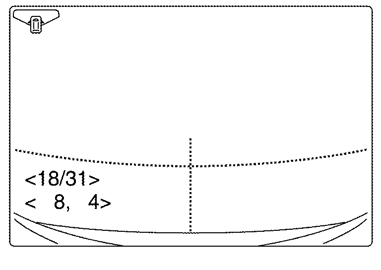
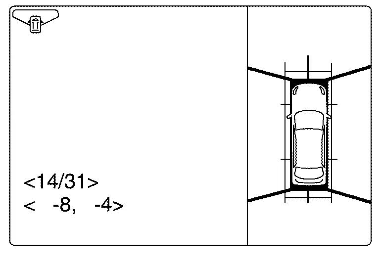
On the adjustment screen of each camera, adjust the parameter by touching the “AXIS X” button, “AXIS Y” button, and “ROTATE” button to place the calibration marker shown on the camera screen on the target line drawn on the ground.
Adjustment range Rotation direction (Center dial) : 31 patterns (16 on the center) Upper/lower direction (upper/lower switch) : −22 – 22 Left/right direction (left/right switch) : −22 – 22 -
Touch “APPLY” button on the CONSULT screen. “PRCSNG” is displayed and adjustment results are shown on the camera screen.
CAUTION:
Check that “PRCSNG” is displayed. Never perform other operations while “PRCSNG” is displayed.
-
Touch “OK” button on the CONSULT screen. “PRCSNG” is displayed and adjustment results are written to the around view monitor control unit.
CAUTION:
Check that “PRCSNG” is displayed. Never perform other operations while “PRCSNG” is displayed.
>>
GO TO 6.
PERFORM “FINE TUNING OF BIRDS-EYE VIEW”
This mode is designed to align the boundary between each camera image that could not be aligned in the “Calibrating Camera Image” mode.
CONSULT
-
Select “FINE TUNING OF BIRDS-EYE VIEW” by touching CONSULT screen.
-
On the adjustment screen of each camera, adjust the parameter by touching the “AXIS X” button, “AXIS Y” button”, and “ROTATE” button to place the calibration marker shown on the camera screen on the target line drawn on the ground.
 NOTE:
NOTE:
Touch “SELECT” button on the CONSULT screen to select the target camera.
-
Touch “APPLY” button on the CONSULT screen. “PRCSNG” is displayed and adjustment results are shown on the camera screen.
CAUTION:
Check that “PRCSNG” is displayed. Never perform other operations while “PRCSNG” is displayed.
-
Touch “OK” button on the CONSULT screen. “PRCSNG” is displayed and adjustment results are written to the around view monitor control unit.
CAUTION:
-
Check that “PRCSNG” is displayed. Never perform other operations while “PRCSNG” is displayed.
-
After pressing the “OK” button, never press buttons other than the “BACK” button.
NOTE:
-
It can be initialized to the NISSAN factory default condition with “Initialize Camera Image Calibration”.
-
The adjustment value is cancelled in this mode by performing “Initialize Camera Image Calibration”.
-
>>
Calibration End.
 Predictive Course Line Center Position Adjustment
Description
Adjust the center position of the predictive course line of the rear view monitor if it is shifted.
Work Procedure
DRIVING
Drive the vehicle straight ahead 100 m (328...

Other information:
Nissan Murano (Z52) 2015-2024 Service Manual: Front Wiper Arm
Exploded View 1. Front wiper blade (RH) 2. Front wiper arm (RH) 3. Front wiper arm cover (RH) 4. Front wiper arm cover (LH) 5. Front wiper arm (LH) 6. Front wiper blade (LH) Removal and Installation REMOVALOperate the front wiper arms into the auto stop position...
Nissan Murano (Z52) 2015-2024 Service Manual: Exterior Lamp Battery Saver System
System Description SYSTEM DIAGRAMSignal transmission function list Signal name Input Output Description Combination switch signal Combination switch (lighting and turn signal switch) BCM Transmits the combination switch signal to the BCM. High beam request signal BCM IPDM E/R (CAN) Combination meter (CAN) Transmits the high beam request signal via CAN communication...
Categories
- Manuals Home
- Nissan Murano Owners Manual
- Nissan Murano Service Manual
- Warning lights
- Shift lock release
- High Beam Assist (if so equipped)
- New on site
- Most important about car
Autolight system
The autolight system allows the headlights to turn on and off automatically. The autolight system can:
Turn on the headlights, front parking, tail, license plate and instrument panel lights automatically when it is dark. Turn off all the lights (except daylight running lights) when it is light. Keep all the lights on for a period of time after you place the ignition switch in the OFF position and all doors are closed.