Nissan Murano: Brake System :: Basic Inspection / Brake Booster
VACUUM INSPECTION
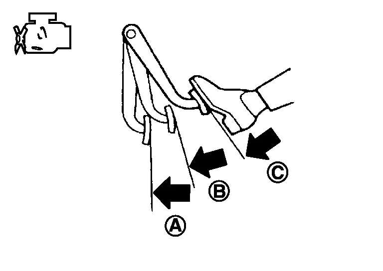
Idle the engine for one minute to apply vacuum to the brake booster. Stop the engine. Depress the brake pedal several times at five second intervals until the accumulated vacuum is released to atmospheric pressure. Check that the clearance between brake pedal and dash lower panel gradually increases (A —>B —>C) each time the brake pedal is depressed during this operation.
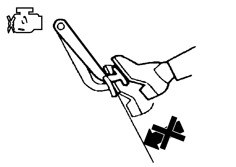
Depress the brake pedal with the engine running. Then stop the engine while holding down the brake pedal. Check that the brake pedal stroke does not change after holding down the brake pedal for 30 seconds or more.
 NOTE:
NOTE:
A slight impact with a small click may be felt on the pedal when the brake pedal is fully depressed. This is normal brake system operation.
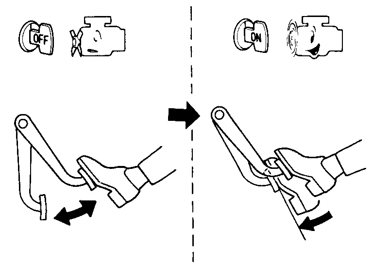
OPERATION
Depress the brake pedal several times at five second intervals with the engine stopped. Start the engine with the brake pedal fully depressed. Check that the clearance between brake pedal and dash lower panel decreases.
NOTE:
A slight impact with a small click may be felt on the pedal when the brake pedal is fully depressed. This is normal brake system operation.
 Brake Master Cylinder
Inspection
Check for brake fluid leakage at the following areas:
Master cylinder mounting face
Reservoir tank mounting face
Sub tank mounting face
Brake tube and brake tube connections
Brake hose and brake hose connections
If any brake fluid leakage is found, repair as necessary...
 Front Disc Brake. Disc Brake Rotor
Inspection
Check for uneven wear of the disc brake rotor using a micrometer. Replace the disc brake rotor if the thickness is below the wear limit. Thickness variation (measured at 8 positions)
: Refer to Front Disc Brake...
Other information:
Nissan Murano (Z52) 2015-2024 Service Manual: U0073 Communication Bus a Off
DTC Description DTC DETECTION LOGICTCM communication blockage lasts for 2 seconds or more when turning ON the ignition switch. (Communication not established.) DTC CONSULT screen terms (Trouble diagnosis content) DTC detection condition U0073 COMM BUS A OFF (Control Module Communication Bus A Off) Diagnosis condition When turning ON the ignition switch Signal CAN communication Threshold TCM communication blockage (Communication not established) Diagnosis delay time Last for 2 seconds or more POSSIBLE CAUSEHarness or connector (CAN communication line is error)FAIL-SAFE Selector shock is large Start is slow Acceleration is slow Lock-up is not performed DTC Confirmation Procedure PREPARATION BEFORE WORK If another “DTC CONFIRMATION PROCEDURE” occurs just before, turn ignition switch OFF and wait for at least 10 seconds, then perform the next test...
Nissan Murano (Z52) 2015-2024 Service Manual: Body Side Trim
Exploded View 1. Center pillar upper finisher 2. Front door welt 3. Front pillar finisher 4. Dash side finisher 5. Front outer kicking plate 6. Front inner kicking plate 7. Center pillar lower finisher 8. Rear door welt 9...
Categories
- Manuals Home
- Nissan Murano Owners Manual
- Nissan Murano Service Manual
- Intelligent Forward Collision Warning (I-FCW)
- High Beam Assist (if so equipped)
- All-Wheel Drive (AWD) (if so equipped)
- New on site
- Most important about car
Front manual seat adjustment (if so equipped)
Your vehicle seats can be adjusted manually. For additional information about adjusting the seats, refer to the steps outlined in this section.
Forward and backward
