Nissan Murano: Back Door Trim / Back Door Upper Finisher
Nissan Murano (Z52) 2015-2024 Service Manual / Body Interior / Interior :: Removal and Installation / Back Door Trim / Back Door Upper Finisher
REMOVAL
Release back door upper finisher (1) upper pawls as shown.
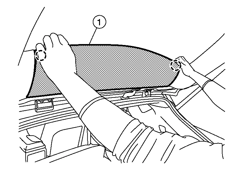
 : Pawl
Release back door upper finisher (1) lower pawls as shown.
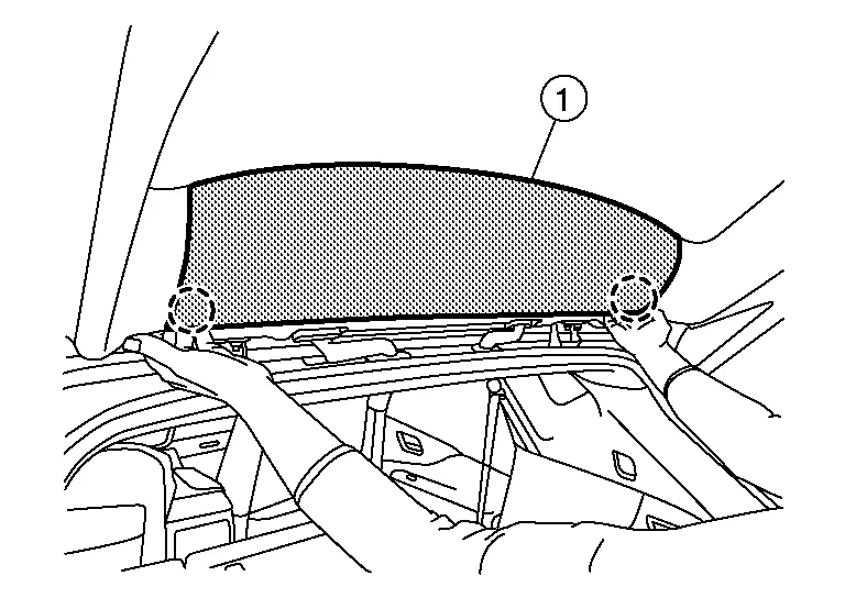
: Pawl
Release metal clips and remove back door upper finisher (1).
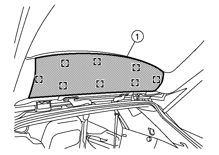
 : Metal clip
INSTALLATION
Installation is in the reverse order of removal.
CAUTION:
-
Visually check metal clips for deformation and damage during installation. Replace with new ones if necessary.
-
When installing back door upper finisher, check that metal clips are securely placed in body panel holes.
 Back Door Trim
Exploded View
1.
Back door upper finisher
2.
Back door side finisher (RH)
3.
Back door lower finisher
4.
Back door pull handle
5.
Automatic back door close switch (if equipped)
6...
 Back Door Lower Finisher
Removal and Installation
REMOVALRelease clips from back door lower finisher (1) using a suitable tool.
: Clip
Remove back door pull handle. Refer to Exploded View...
Other information:
Nissan Murano (Z52) 2015-2024 Service Manual: Periodic Maintenance. Engine Coolant
System Inspection WARNING: Do not remove the radiator cap or reservoir tank cap when the engine is hot. Serious burns could occur from high-pressure engine coolant escaping from the cooling system. When removing the radiator cap or reservoir tank cap, wrap a thick cloth around the cap and slowly turn it a quarter turn to allow built-up pressure to escape...
Nissan Murano (Z52) 2015-2024 Service Manual: Configuration (around View Monitor Control Unit)
Description Vehicle specification needs to be written with CONSULT because it is not written after replacing around view monitor control unit.Configuration has three functions as follows Function Description READ CONFIGURATION Reads the Nissan Murano vehicle configuration of current around view monitor control unit...
Categories
- Manuals Home
- Nissan Murano Owners Manual
- Nissan Murano Service Manual
- Warning lights
- All-Wheel Drive (AWD) (if so equipped)
- Fuel recommendation
- New on site
- Most important about car
Unfastening the seat belts. Checking seat belt operation
Unfastening the seat belts

To unfasten the seat belt, press the button
on the buckle  . The seat belt
automatically
retracts.
. The seat belt
automatically
retracts.
Copyright © 2026 www.nimurano.com