Nissan Murano: Door & Lock :: Ecu Diagnosis Information / Automatic Back Door Control Module
 NOTE:
NOTE:
The following table includes information (items) inapplicable to this Nissan Murano vehicle. For information (items) applicable to this vehicle, refer to CONSULT display items.
| Monitor Item | Condition | Value/Status | |
|---|---|---|---|
| SPINDLE SENSOR LH | Back door: Moving | 0 – 65535 | |
| SPINDLE LH SPEED | Back door: Moving | 0 – 6553.5 | |
| SPINDLE MOTOR LH DUTY | Back door: Moving | 0 – 255 | |
| VHCL SPEED MTR | While driving | Equivalent to speedometer reading | |
| VHCL SPEED ABS | While driving | Equivalent to speedometer reading | |
| MAIN SW | Automatic back door main switch | OFF | OFF |
| ON | ON | ||
| AUTO BD SW | Automatic back door switch | Release | OFF |
| Press | ON | ||
| BK DOOR CL SW | Automatic back door close switch | Release | OFF |
| Press | ON | ||
| BACK DOOR LOCK STATUS | Back door lock | Lock | OFF |
| Unlock | ON | ||
| PKB SW | Parking brake | Not applied | OFF |
| Applied | ON | ||
| OPEN SW | Back door | Half latch/fully closed | OFF |
| Open | ON | ||
| CLOSE SW | Back door | Half latch/fully closed | OFF |
| Applied | ON | ||
| HALF LATCH SW | Back door | Open/fully closed | OFF |
| Half latch | ON | ||
| TOUCH SEN RH | Touch sensor RH | Other than below | OFF |
| Detect obstruction | ON | ||
| TOUCH SEN LH | Touch sensor LH | Other than below | OFF |
| Detect obstruction | ON | ||
| P RANGE IND | Selector lever | Other than P position | OFF |
| P position | ON | ||
| RKE REQ | Intelligent Key button (back door) | Release | OFF |
| Press (more than 0.5 seconds) | MOVE | ||
| Press (just after) | REV | ||
| IGN SW | Ignition switch | Other than ON position | OFF |
| ON position | ON | ||
| SPINDLE LH ENCODER A | Automatic back door | Not operate | No change HI or LO |
| Operated | Change HI or LO | ||
| SPINDLE LH ENCODER B | Automatic back door | Not operate | No change HI or LO |
| Operated | Change HI or LO | ||
| DESTINATION | — | OTHER | |
| AUTO BCK DR POS INITIAL | Calibration of automatic back door position information | Not complete | YET |
| Complete | DONE | ||
| AUTO BCK DR POS LEARN | Additional service when removing battery negative terminal | Not complete | YET |
| Complete | DONE | ||
| SPINDLE SENSOR RH | Back door: Moving | 0 – 65535 | |
| SPINDLE RH SPEED | Back door: Moving | 0 – 6553.5 | |
| SPINDLE MOTOR RH DUTY | Back door: Moving | 0 – 255 | |
| SPINDLE RH ENCODER A | Automatic back door | Not operated | No change HI or LO |
| Operate | Change HI or LO | ||
| SPINDLE RH ENCODER B | Automatic back door | Not operated | No change HI or LO |
| Operate | Change HI or LO | ||
| TRANSMISSION TYPE | — | AT/CVT | |
TERMINAL LAYOUT
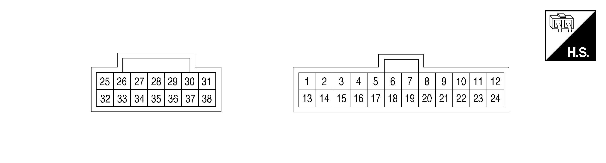
PHYSICAL VALUES
|
Terminal No. (Wire color) | Description | Condition |
Voltage (Approx.) | |||
|---|---|---|---|---|---|---|
| (+) | (–) | Signal name | Input/Output | |||
|
1 (BR) |
13 (V) |
Touch sensor RH signal | Input | Touch sensor RH | Detect obstruction | 1.8 – 2.72 V |
| Other than above | 2.72 – 7.27 V | |||||
|
2 (G/W) |
13 (V) |
Touch sensor LH signal | Input | Touch sensor LH | Detect obstruction | 1.8 – 2.72 V |
| Other than above | 2.72 – 7.27 V | |||||
|
3 (L/G) |
Ground | Half latch switch signal | Input | Back door | Open | 0 V |
| Fully closed/half latch | Battery voltage | |||||
|
4 (B/L) |
Ground | Ground | — | — | 0 V | |
|
5 (BR/W) |
Ground | Close switch signal | Input | Back door | Fully closed | 0 V |
| Open/half latch | Battery voltage | |||||
|
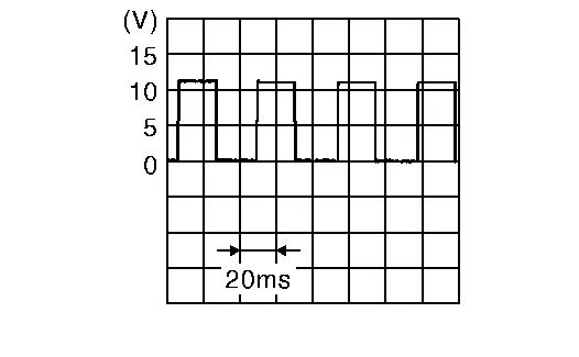
6 (V/W) |
Ground | Encoder LH A signal | Input | Back door | Moving (auto or manual) |
Waveform width changes according to back door open/close speed |
| When stopped | 0 V or Battery voltage | |||||
|
7 (Y) |
Ground | Encoder LH B signal | Input | Back door | Moving (auto or manual) |
Waveform width changes according to back door open/close speed |
| When stopped | 0 V or Battery voltage | |||||
|
8 (W/V) |
Ground | Encoder RH A signal | Input | Back door | Moving (auto or manual) |
Waveform width changes according to back door open/close speed |
| When stopped | 0 V or Battery voltage | |||||
|
9 (G/BR) |
Ground | Encoder RH B signal | Input | Back door | Moving (auto or manual) |
Waveform width changes according to back door open/close speed |
| When stopped | 0 V or Battery voltage | |||||
|
10 (BR/Y) |
Ground | Ground | — | — | 0 V | |
|
11 (BR/Y) |
Ground | Open switch signal | Input | Back door | Open | 0 V |
| Half latch/fully closed | Battery voltage | |||||
|
12 (P) |
Ground | CAN-Low | Input/Output | — | — | |
|
13 (V) |
Ground | Touch sensor ground | Input | — | 0.01 – 0 V | |
|
19 (B/W) |
Ground | Encoder LH power supply | Output | — | Battery voltage | |
|
20 (Y/O) |
Ground | Encoder RH power supply | Output | — | Battery voltage | |
|
21 (G/W) |
Ground | Encoder ground | — | — | 0 V | |
|
22 (L) |
Ground | Automatic back door switch | Input | Automatic back door switch | Pressed | Battery voltage |
| Released | 0 V | |||||
|
23 (Y/GR) |
Ground | Automatic back door close switch | Input | Automatic back door close switch | Pressed | Battery voltage |
| Released | 0 V | |||||
|
24 (L) |
Ground | CAN-High | Input/Output | — | — | |
|
25 (P) |
Ground | Power supply (BAT) | Input | — | Battery voltage | |
|
27 (B) |
Ground | Spindle motor LH (open) | Output | — | Battery voltage | |
|
29 (B) |
Ground | Spindle motor RH (open) | Output | Back door | Auto open operation | Battery voltage |
|
31 (B) |
Ground | Back door closure motor (open) | Output | Back door | Open operation | Battery voltage |
| Other than above | 0 V | |||||
|
32 (B) |
Ground | Ground | — | — | 0 V | |
|
34 (W) |
Ground | Spindle motor LH (close) | Output | Back door | Auto close operation | Battery voltage |
|
36 (W) |
Ground | Spindle motor RH (close) | Output | Back door | Auto close operation | Battery voltage |
|
37 (LG) |
Ground | Back door warning buzzer | Output | Automatic back door warning buzzer | Sounding | 0 V |
| Not sounding | Battery voltage | |||||
|
38 (W) |
Ground | Back door closure motor (close) | Output | Back door | Close operation | Battery voltage |
| Other than above | 0 V | |||||
| Display contents of CONSULT | Fail-safe | Cancellation |
|---|---|---|
| U1000 CAN COMM CIRCUIT | Inhibit automatic back door operation | Return to normal status. |
| U1010 CONTROL UNIT(CAN) | Inhibit automatic back door operation | Return to normal status. |
| U1320 REPROGRAMMING | Inhibit automatic back door operation | Return to normal status. |
| B2401 IGN OPEN | Inhibit automatic back door operation | Automatic back door control module detects ignition switch ON signal via CAN communication. |
| B2409 HALF LATCH SW | Inhibit automatic back door operation | Automatic back door control module detects that half latch switch changes from ON to OFF when back door fully closes. |
| B2416 TOUCH SEN R OPEN | Inhibit automatic back door operation | Return to normal status. |
| B2417 TOUCH SEN L OPEN | Inhibit automatic back door operation | Return to normal status. |
| B2419 OPEN SW | Inhibit automatic back door operation | Reconnect battery. |
| B2420 CLOSE SW | Inhibit automatic back door operation | Reconnect battery. |
| B2422 BACK DOOR STATE | Inhibit automatic back door operation | Half latch switch is ON from OFF. |
| B2423 ABD MTR TIME OUT | Inhibit automatic back door operation | At least 180 seconds are passed after automatic back door operation is inhibited. |
| B2426 SPINDLE SENSOR LH | Inhibit automatic back door operation | Return to normal status. |
| B2427 SPINDLE SENSOR RH | Inhibit automatic back door operation | Return to normal status. |
| B2428 AUTO BACK DR CNT UNIT | Inhibit automatic back door operation | Return to normal status. |
| B242A CLSR CONDITION | Inhibit automatic back door operation | Reconnect battery. |
| B242B DETECT SENSOR POWER SUPPLY | Inhibit hands free operation | Return to normal status. |
| B242C HANDS FREE SEN CONTROL UNIT | Inhibit hands free operation | Return to normal status. |
| B242D HANDS FREE SENSOR 1 | Inhibit hands free operation | Return to normal status. |
| B242E HANDS FREE SENSOR 2 | Inhibit hands free operation | Return to normal status. |
| B242F ABD BUZZER | Inhibit hands free operation | Return to normal status. |
If some DTCs are displayed at the same time, perform inspections one by one based on the following priority chart.
| Priority | DTC |
|---|---|
| 1 |
|
| 2 |
|
NOTE:
Details of time display
-
1 - 39: Displayed if any previous malfunction is present when current condition is normal. It increases 1 → 2 → 3...38 → 39 after returning to the normal condition whenever ignition switch OFF → ON. The counter remains at 39 even if the number of cycles exceeds it. It is counted from 1 again when ignition switch OFF → ON after returning to the normal condition if the malfunction is detected again.
| CONSULT display | Fail-safe | Reference page |
|---|---|---|
| U1000: CAN COMM CIRCUIT | × | DTC Description |
| U1010: CONTROL UNIT(CAN) | × | DTC Description |
| U1320: REPROGRAMMING | × | DTC Description |
| B2401: IGN OPEN | × | DTC Description |
| B2409: HALF LATCH SW | × | DTC Description |
| B2416: TOUCH SEN R OPEN | × | DTC Description |
| B2417: TOUCH SEN L OPEN | × | DTC Description |
| B2419: OPEN SW | × | DTC Description |
| B2420: CLOSE SW | × | DTC Description |
| B2422: BACK DOOR STATE | × | DTC Description |
| B2423: ABD MTR TIME OUT | × | DTC Description |
| B2426: SPINDLE SENSOR LH | × | DTC Description |
| B2427: SPINDLE SENSOR RH | × | DTC Description |
| B2428: AUTO BACK DR CNT UNIT | × | DTC Description |
| B242A: CLSR CONDITION | × | DTC Description |
| B242B: DETECT SENSOR POWER SUPPLY | × | DTC Description |
| B242C: HANDS FREE SEN CONTROL UNIT | × | DTC Description |
| B242D: HANDS FREE SENSOR 1 | × | DTC Description |
| B242E: HANDS FREE SENSOR 2 | × | DTC Description |
| B242F: ABD BUZZER | × | DTC Description |

 Motion Activated Back Door Control Unit
Reference Value
TERMINAL LAYOUTPHYSICAL VALUES
Terminal No.
(Wire color) Description Condition
Voltage
(Approx.)
(+) (–) Signal name Input/Output
1
(L)
Ground
Serial communication
Input/Output
—
—
2
(V)
Ground
Power supply (BAT)
Input
—
Battery voltage
3
(B)
Ground
Ground
—
—
0 V
4
(W)
Ground
Motion activated back door sensor (upper) input signal
Input
—
—
5
(W)
Ground
Motion activated back door sensor (upper) output signal
Input
—
—
6
(W)
Ground
Motion activated back door sensor (lower) input signal
Input
—
—
7
(W)
Ground
Motion activated back door sensor (lower) output signal
Input
—
—
NOTE:
Voltage generated in communication circuit between motion activated back door sensor and motion activated back door control unit is extremely low and therefore cannot be measured...
Other information:
Nissan Murano (Z52) 2015-2024 Owners Manual: System temporarily unavailable
The following are conditions in which the ICC system may be temporarily unavailable. In these instances, the ICC system may not cancel and may not be able to maintain the selected following distance from the vehicle ahead. Condition A Under the following conditions, the ICC system is automatically canceled...
Nissan Murano (Z52) 2015-2024 Service Manual: B2601 Shift Position
DTC Description DTC DETECTION LOGICNOTE: If DTC B2601 is displayed with DTC U1000, first perform the trouble diagnosis for DTC U1000. Refer to DTC Description. If DTC B2601 is displayed with DTC U1010, first perform the trouble diagnosis for DTC U1010...
Categories
- Manuals Home
- Nissan Murano Owners Manual
- Nissan Murano Service Manual
- Turning the AEB system on/off
- Vehicle Dynamic Control (VDC) OFF switch
- How to enable/disable the LDW system
- New on site
- Most important about car
Vehicle security system

Your vehicle has two types of security systems:
Vehicle security system NISSAN Vehicle Immobilizer SystemThe vehicle security system provides visual and audible alarm signals if someone opens the doors, liftgate or the hood when the system is armed. It is not, however, a motion detection type system that activates when a vehicle is moved or when a vibration occurs.