Nissan Murano: Ecu Diagnosis Information / Around View Monitor Control Unit
 NOTE:
NOTE:
The following table includes information (items) inapplicable to this Nissan Murano vehicle. For information (items) applicable to this vehicle, refer to CONSULT display items.
| Monitor Item | Condition | Value/Status |
|---|---|---|
| CAMERA OFF SIGNAL | CAMERA switch ON. | Off |
| CAMERA switch OFF. | On | |
| CAMERA SWITCH SIGNAL | CAMERA switch OFF. | Off |
| CAMERA switch ON. | On | |
| DR-SIDE CAMERA IMAGE SIGNAL | Side camera LH inoperative. | NG |
| Side camera LH operative. | OK | |
| F-CAMERA IMAGE SIGNAL | Front camera inoperative. | NG |
| Front camera operative. | OK | |
| ILL | Illumination OFF. | Off |
| Illumination ON. | On | |
| PA-SIDE CAMERA IMAGE SIG | Side camera RH inoperative. | NG |
| Side camera RH operative. | OK | |
| REAR CAMERA IMAGE SIGNAL | Rear view camera inoperative. | NG |
| Rear view camera operative. | OK | |
| REVERSE SIGNAL | When selector lever is in any position other than R (reverse). | Off |
| When selector lever in R (reverse). | On | |
| ST ANGLE SENSOR SIGNAL | Around view monitor control unit is not receiving steering angle sensor signal. | Off |
| Around view monitor control unit is receiving steering angle sensor signal. | On | |
| ST ANGLE SENSOR TYPE | Steering angle sensor type. | Absolute |
| STEERING GEAR RATIO TYPE | Steering gear ratio type. | Type 0 |
| STEERING POSITION | Left hand drive Nissan Murano vehicle. | LHD |
| Right hand drive vehicle. | RHD | |
| TURN SIGNAL | Turn signal OFF. | Off |
| Turn signal ON. | On | |
| Nissan Murano Vehicle SPEED SIGNAL | While driving, equivalent to speedometer reading | mph, km/h |
TERMINAL LAYOUT
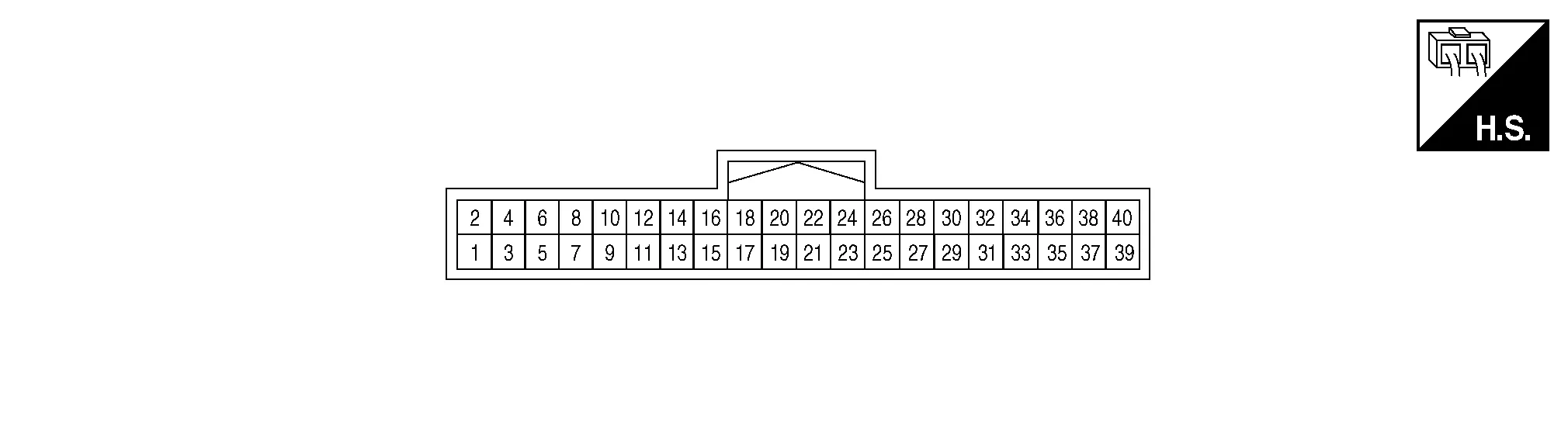
PHYSICAL VALUES
|
Terminal (Wire color) | Description | Condition |
Reference value (Approx.) | ||
|---|---|---|---|---|---|
| + | – | Signal name | Input/Output | ||
|
3 (Shield) |
— | Video output shield | — | — | — |
|
4 (B) |
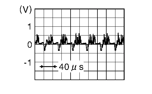
Ground | Video output signal | Output |
[Ignition switch ON]
|
|
|
5 (B) |
— | Front camera ground | — | [Ignition switch ON] | 0 V |
|
6 (R) |
5 (B) |
Front camera power supply | Output | [Ignition switch ON] | 6.0 V |
|
7 (Shield) |
— | Front camera video ground | — | [Ignition switch ON] | 0 V |
|
8 (W) |
7 (Shield) |
Front camera video signal | Input |
[Ignition switch ON]
|
|
|
9 (W) |
— | Door mirror RH camera ground | — | [Ignition switch ON] | 0 V |
|
10 (R) |
9 (W) |
Door mirror RH camera power supply | Output | [Ignition switch ON] | 6.0 V |
|
11 (Shield) |
— | Door mirror RH camera video ground | — | [Ignition switch ON] | 0 V |
|
12 (B) |
11 (Shield) |
Door mirror RH camera video signal | Input |
[Ignition switch ON]
|
|
|
13 (W) |
— | Door mirror LH camera ground | — | [Ignition switch ON] | 0 V |
|
14 (R) |
13 (W) |
Door mirror LH camera power supply | Output | [Ignition switch ON] | 6.0 V |
|
15 (Shield) |
— | Door mirror LH camera video ground | — | [Ignition switch ON] | 0 V |
|
16 (B) |
15 (Shield) |
Door mirror LH camera video signal | Input |
[Ignition switch ON]
|
|
|
17 (R) |
— | Rear view camera ground | — | [Ignition switch ON] | 0 V |
|
18 (W) |
17 (R) |
Rear view camera power supply | Output | [Ignition switch ON] | 6.0 V |
|
19 (Shield) |
— | Rear view camera video ground | — | [Ignition switch ON] | 0 V |
|
20 (B) |
19 (Shield) |
Rear view camera video signal | Input |
[Ignition switch ON]
|
|
|
24 (Y) |
— | CAN-Low | Input/Output | — | — |
|
26 (L) |
— | CAN-High | Input/Output | — | — |
|
32 (G) |
39 (B) |
Reverse signal | Input |
[Ignition switch ON]
|
Battery voltage |
|
39 (B) |
— | Ground | — | [Ignition switch ON] | 0 V |
|
40 (LG) |
39 (B) |
Ignition signal | Input | [Ignition switch ON or START] | Battery voltage |
|
DTC Display contents of CONSULT | Malfunction detection condition | Fail-safe condition |
|---|---|---|
|
U0428: ST ANGLE SENSOR CALIBRATION |
Neutral position adjustment of steering angle sensor is not complete. |
|
| U1000: CAN COMM CIRCUIT | When around view monitor control unit cannot transmit/receive CAN communication signal continuously for 2 seconds or more. |
The following functions are stopped
|
| U111A: REAR CAMERA IMAGE SIGNAL | No-signal status of rear camera image signal is continued for 500 ms or more while ignition switch is ON. | Camera image is not displayed (gray screen display). |
| U111B: SIDE CAMERA RH IMAGE SIGNAL | No-signal status of side camera RH image signal is continued for 500 ms or more while ignition switch is ON. | |
| U111C: FRONT CAMERA IMAGE SIGNAL | No-signal status of front camera image signal is continued for 500 ms or more while ignition switch is ON. | |
| U111D: SIDE CAMERA LH IMAGE SIGNAL | No-signal status of side camera LH image signal is continued for 500 ms or more while ignition switch is ON. | |
| U1232: ST ANGLE SEN CALIB | Neutral position adjustment of steering angle sensor is performed. NG signal from steering angle sensor is received. |
|
| U1302: CAMERA POWER VOLT |
Camera power supply voltage does not satisfy the following conditions for 2 seconds or more when ignition switch is turned ON:
|
Camera power output is stopped. |
| U1304: CAMERA IMAGE CALIB |
|
Unmatched icon  display (red) is displayed (applicable for unmatched camera only). display (red) is displayed (applicable for unmatched camera only). |
| Other | When around view monitor control unit is not normal. | Switch to camera screen is not allowed. |
| When communication between around view monitor control unit and each camera is not normal. | On applicable camera screen,  marking (Red) is displayed. marking (Red) is displayed. |
|
| When communication line between around view monitor control unit and each camera image line is affected by electromagnetic noises. | On applicable camera image screen, display (Blue) is displayed. |
If multiple DTCs are detected simultaneously, check them one by one depending on the following DTC inspection priority chart:
| Priority | Detected items (DTC) |
|---|---|
| 1 |
|
| 2 |
|
| DTC | CONSULT display | Refer to |
|---|---|---|
| U0428 | ST ANGLE SENSOR CALIBRATION | DTC Description |
| U1000 | CAN COMM CIRCUIT | DTC Description |
| U1010 | CONTROL UNIT (CAN) | DTC Description |
| U111A | REAR CAMERA IMAGE SIGNAL | DTC Description |
| U111B | SIDE CAMERA RH IMAGE SIGNAL | DTC Description |
| U111C | FRONT CAMERA IMAGE SIGNAL | DTC Description |
| U111D | SIDE CAMERA LH IMAGE SIGNAL | DTC Description |
| U1232 | ST ANGLE SEN CALIB | DTC Description |
| U1302 | CAMERA POWER VOLT | DTC Description |
| U1304 | CAMERA IMAGE CALIB | DTC Description |
| U1305 | CONFIG UNFINISH | DTC Description |
 Av Control Unit
L..

Other information:
Nissan Murano (Z52) 2015-2024 Service Manual: Auto Light System
System Description SYSTEM DIAGRAMSignal transmission function list Signal name Input Output Description Combination switch signal Combination switch (lighting and turn signal switch) BCM Transmits the combination switch signal to the BCM. Optical sensor signal Optical sensor BCM Transmits the optical sensor signal to the BCM...
Nissan Murano (Z52) 2015-2024 Service Manual: P014c A/f Sensor 1
DTC Description DTC DETECTION LOGICTo judge malfunctions, this diagnosis measures response time of the A/F signal computed by ECM from the A/F sensor 1 signal. The time is compensated by engine operating (speed and load), fuel feedback control constant, and the A/F sensor 1 temperature index...
Categories
- Manuals Home
- Nissan Murano Owners Manual
- Nissan Murano Service Manual
- GAS STATION INFORMATION
- Memory storage function (key-link)
- Tire rotation
- New on site
- Most important about car
Front manual seat adjustment (if so equipped)
Your vehicle seats can be adjusted manually. For additional information about adjusting the seats, refer to the steps outlined in this section.
Forward and backward
