Nissan Murano: Ecu Diagnosis Information / Around View Monitor Control Unit
 NOTE:
NOTE:
The following table includes information (items) inapplicable to this Nissan Murano vehicle. For information (items) applicable to this vehicle, refer to CONSULT display items.
| Monitor Item | Condition | Value/Status |
|---|---|---|
| CAMERA OFF SIGNAL | CAMERA switch ON. | Off |
| CAMERA switch OFF. | On | |
| CAMERA SWITCH SIGNAL | CAMERA switch OFF. | Off |
| CAMERA switch ON. | On | |
| DR-SIDE CAMERA IMAGE SIGNAL | Side camera LH inoperative. | NG |
| Side camera LH operative. | OK | |
| F-CAMERA IMAGE SIGNAL | Front camera inoperative. | NG |
| Front camera operative. | OK | |
| ILL | Illumination OFF. | Off |
| Illumination ON. | On | |
| PA-SIDE CAMERA IMAGE SIG | Side camera RH inoperative. | NG |
| Side camera RH operative. | OK | |
| REAR CAMERA IMAGE SIGNAL | Rear view camera inoperative. | NG |
| Rear view camera operative. | OK | |
| REVERSE SIGNAL | When selector lever is in any position other than R (reverse). | Off |
| When selector lever in R (reverse). | On | |
| ST ANGLE SENSOR SIGNAL | Around view monitor control unit is not receiving steering angle sensor signal. | Off |
| Around view monitor control unit is receiving steering angle sensor signal. | On | |
| ST ANGLE SENSOR TYPE | Steering angle sensor type. | Absolute |
| STEERING GEAR RATIO TYPE | Steering gear ratio type. | Type 0 |
| STEERING POSITION | Left hand drive Nissan Murano vehicle. | LHD |
| Right hand drive vehicle. | RHD | |
| TURN SIGNAL | Turn signal OFF. | Off |
| Turn signal ON. | On | |
| Nissan Murano Vehicle SPEED SIGNAL | While driving, equivalent to speedometer reading | mph, km/h |
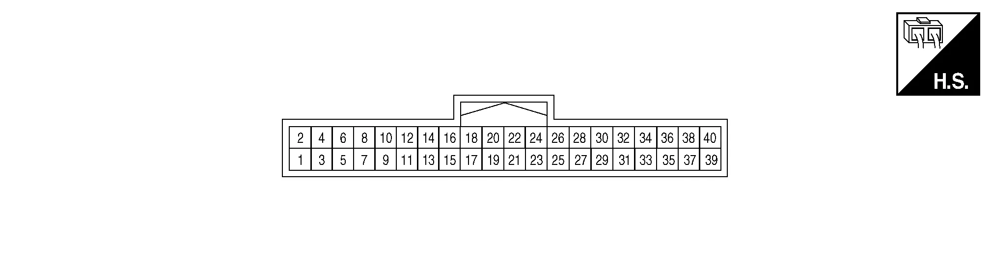
TERMINAL LAYOUT
PHYSICAL VALUES
|
Terminal (Wire color) | Description | Condition |
Reference value (Approx.) | ||
|---|---|---|---|---|---|
| + | – | Signal name | Input/Output | ||
|
3 (Shield) |
— | Video output shield | — | — | — |
|
4 (B) |
Ground | Video output signal | Output |
[Ignition switch ON]
|
|
|
5 (B) |
— | Front camera ground | — | [Ignition switch ON] | 0 V |
|
6 (R) |
5 (B) |
Front camera power supply | Output | [Ignition switch ON] | 6.0 V |
|
7 (Shield) |
— | Front camera video ground | — | [Ignition switch ON] | 0 V |
|
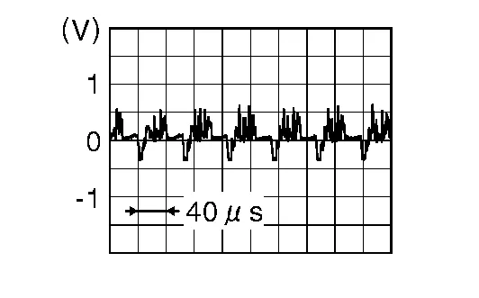
8 (W) |
7 (Shield) |
Front camera video signal | Input |
[Ignition switch ON]
|
|
|
9 (W) |
— | Door mirror RH camera ground | — | [Ignition switch ON] | 0 V |
|
10 (R) |
9 (W) |
Door mirror RH camera power supply | Output | [Ignition switch ON] | 6.0 V |
|
11 (Shield) |
— | Door mirror RH camera video ground | — | [Ignition switch ON] | 0 V |
|
12 (B) |
11 (Shield) |
Door mirror RH camera video signal | Input |
[Ignition switch ON]
|
|
|
13 (W) |
— | Door mirror LH camera ground | — | [Ignition switch ON] | 0 V |
|
14 (R) |
13 (W) |
Door mirror LH camera power supply | Output | [Ignition switch ON] | 6.0 V |
|
15 (Shield) |
— | Door mirror LH camera video ground | — | [Ignition switch ON] | 0 V |
|
16 (B) |
15 (Shield) |
Door mirror LH camera video signal | Input |
[Ignition switch ON]
|
|
|
17 (R) |
— | Rear view camera ground | — | [Ignition switch ON] | 0 V |
|
18 (W) |
17 (R) |
Rear view camera power supply | Output | [Ignition switch ON] | 6.0 V |
|
19 (Shield) |
— | Rear view camera video ground | — | [Ignition switch ON] | 0 V |
|
20 (B) |
19 (Shield) |
Rear view camera video signal | Input |
[Ignition switch ON]
|
|
|
24 (Y) |
— | CAN-Low | Input/Output | — | — |
|
26 (L) |
— | CAN-High | Input/Output | — | — |
|
32 (G) |
39 (B) |
Reverse signal | Input |
[Ignition switch ON]
|
Battery voltage |
|
39 (B) |
— | Ground | — | [Ignition switch ON] | 0 V |
|
40 (LG) |
39 (B) |
Ignition signal | Input | [Ignition switch ON or START] | Battery voltage |
|
DTC Display contents of CONSULT | Malfunction detection condition | Fail-safe condition |
|---|---|---|
|
U0428: ST ANGLE SENSOR CALIBRATION |
Neutral position adjustment of steering angle sensor is not complete. |
|
| U1000: CAN COMM CIRCUIT | When around view monitor control unit cannot transmit/receive CAN communication signal continuously for 2 seconds or more. |
The following functions are stopped
|
| U111A: REAR CAMERA IMAGE SIGNAL | No-signal status of rear camera image signal is continued for 500 ms or more while ignition switch is ON. | Camera image is not displayed (gray screen display). |
| U111B: SIDE CAMERA RH IMAGE SIGNAL | No-signal status of side camera RH image signal is continued for 500 ms or more while ignition switch is ON. | |
| U111C: FRONT CAMERA IMAGE SIGNAL | No-signal status of front camera image signal is continued for 500 ms or more while ignition switch is ON. | |
| U111D: SIDE CAMERA LH IMAGE SIGNAL | No-signal status of side camera LH image signal is continued for 500 ms or more while ignition switch is ON. | |
| U1232: ST ANGLE SEN CALIB | Neutral position adjustment of steering angle sensor is performed. NG signal from steering angle sensor is received. |
|
| U1302: CAMERA POWER VOLT |
Camera power supply voltage does not satisfy the following conditions for 2 seconds or more when ignition switch is turned ON:
|
Camera power output is stopped. |
| U1304: CAMERA IMAGE CALIB |
|
Unmatched icon  display (red) is displayed (applicable for unmatched camera only). display (red) is displayed (applicable for unmatched camera only). |
| Other | When around view monitor control unit is not normal. | Switch to camera screen is not allowed. |
| When communication between around view monitor control unit and each camera is not normal. | On applicable camera screen,  marking (Red) is displayed. marking (Red) is displayed. |
|
| When communication line between around view monitor control unit and each camera image line is affected by electromagnetic noises. | On applicable camera image screen, display (Blue) is displayed. |
If multiple DTCs are detected simultaneously, check them one by one depending on the following DTC inspection priority chart:
| Priority | Detected items (DTC) |
|---|---|
| 1 |
|
| 2 |
|
| DTC | CONSULT display | Refer to |
|---|---|---|
| U0428 | ST ANGLE SENSOR CALIBRATION | DTC Description |
| U1000 | CAN COMM CIRCUIT | DTC Description |
| U1010 | CONTROL UNIT(CAN) | DTC Description |
| U111A | REAR CAMERA IMAGE SIGNAL | DTC Description |
| U111B | SIDE CAMERA RH IMAGE SIGNAL | DTC Description |
| U111C | FRONT CAMERA IMAGE SIGNAL | DTC Description |
| U111D | SIDE CAMERA LH IMAGE SIGNAL | DTC Description |
| U1232 | ST ANGLE SEN CALIB | DTC Description |
| U1302 | CAMERA POWER VOLT | DTC Description |
| U1304 | CAMERA IMAGE CALIB | DTC Description |
| U1305 | CONFIG UNFINISH | DTC Description |
 Audio Unit
L..

Other information:
Nissan Murano (Z52) 2015-2024 Service Manual: Moonroof Motor Assembly
Exploded View 1. Panoramic roof glass 2. Moonroof drain 3. Wind deflector 4. Glass lid 5. Side trim covers (LH/RH) 6. Front drain hose (LH/RH) 7. Moonroof motor assembly 8. Sunshade motor assembly 9. Moonroof front bracket (LH/RH) 10...
Nissan Murano (Z52) 2015-2024 Service Manual: Front Suspension :: Precaution. Precautions
Precaution for Supplemental Restraint System (SRS) "AIR BAG" and "SEAT BELT PRE-TENSIONER" The Supplemental Restraint System such as “AIR BAG” and “SEAT BELT PRE-TENSIONER”, used along with a front seat belt, helps to reduce the risk or severity of injury to the driver and front passenger for certain types of collisions...
Categories
- Manuals Home
- Nissan Murano Owners Manual
- Nissan Murano Service Manual
- How to enable/disable the LDW system
- All-Wheel Drive (AWD) (if so equipped)
- Fuel recommendation
- New on site
- Most important about car
Unfastening the seat belts. Checking seat belt operation
Unfastening the seat belts

To unfasten the seat belt, press the button
on the buckle  . The seat belt
automatically
retracts.
. The seat belt
automatically
retracts.