Nissan Murano: Brake System :: Removal and Installation / Vacuum Lines
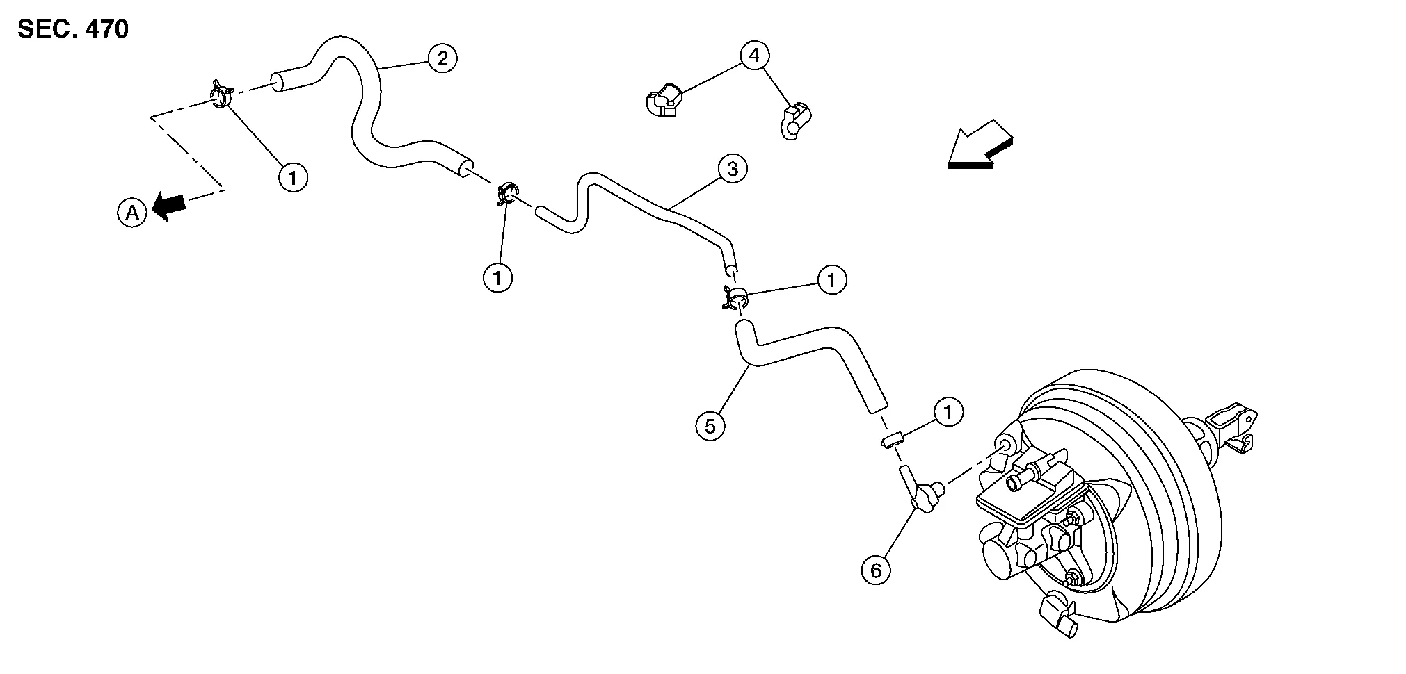
| 1. | Clamp | 2. | Vacuum hose | 3. | Vacuum pipe |
| 4. | Clip | 5. | Vacuum hose | 6. | Check valve |
| A. | To intake manifold collector. Refer to Exploded View. | Front |
REMOVAL
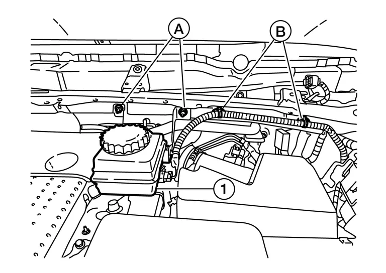
Remove the sub tank bracket nuts (A), release the brake fluid level switch harness clips (B) and position the sub tank assembly (1) aside.
Remove the air cleaner case as an assembly. Refer to Exploded View.
Remove the engine room cover. Refer to Removal and Installation.
If necessary, remove the check valve from the brake booster.
Disconnect the vacuum hose from the check valve.
Disconnect the vacuum hose from the intake manifold collector.
Disconnect the clips from vacuum pipe.
Remove the vacuum hoses and the vacuum pipe.
INSPECTION AFTER REMOVAL
Check for correct installation, damage and deterioration of the vacuum hoses and pipe.
INSTALLATION
Installation is in the reverse order of removal.
CAUTION:
-
Install the vacuum hoses and the vacuum pipe in the correct position. Refer to Exploded View.
-
Install the vacuum hoses onto the vacuum pipe to the specified length (A) or further as shown.
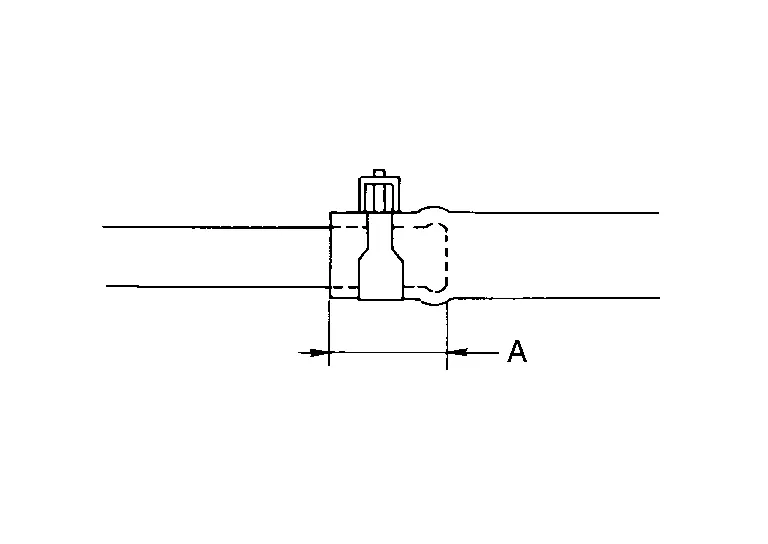
CAUTION:
Do not use lubricating oil during installation.
A : 24 mm (0.94 in) or more
 Brake Booster
Exploded View
1.
Master cylinder assembly
2.
Vacuum sensor
3.
Brake booster
4.
Lock nut
5.
Clevis
6.
Gasket
Removal and Installation
REMOVALRemove instrument lower panel LH...

Other information:
Nissan Murano (Z52) 2015-2024 Service Manual: Telescopic Sensor
Component Function Check DATA MONITOR CONSULT Select “TELESCO PULSE” in “Data Monitor” mode of “AUTO DRIVE POS.”. Check that the function operates normally according to the following conditions: Monitor item Condition Value TELESCO PULSE Steering column Operate (forward) Change (decrease) Operate (backward) Change (increase) Release No change Is the inspection result normal? YES>> Inspection End...
Nissan Murano (Z52) 2015-2024 Service Manual: Brake Pedal Vibration or Operation Sound Occurs
Diagnosis Procedure Brake pedal vibrates and motor sound from ABS actuator and electric unit (control unit) occurs when the engine starts. Brake pedal vibrates during braking. CAUTION: Vibration may be felt when brake pedal is lightly depressed (just placing a foot on it) in the following conditions: This is normal...
Categories
- Manuals Home
- Nissan Murano Owners Manual
- Nissan Murano Service Manual
- System malfunction
- Tire rotation
- All-Wheel Drive (AWD) (if so equipped)
- New on site
- Most important about car
Driver and passenger supplemental knee air bag

Driver’s side
The knee air bag is located in the knee bolster, on the driver’s and passenger’s side. All of the information, cautions and warnings in this manual apply and must be followed. The knee air bag is designed to inflate in higher severity frontal collisions, although it may inflate if the forces in another type of collision are similar to those of a higher severity frontal impact. It may not inflate in certain collisions.

Passenger’s side