Nissan Murano: Unit Disassembly and Assembly / Transaxle Assembly
 |
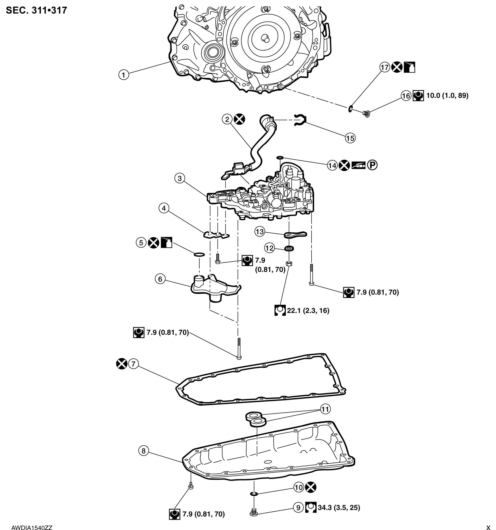
Transaxle assembly |  |
Terminal cord assembly |  |
Control valve |
 |
Bracket |  |
O-ring |  |
Oil strainer assembly |
 |
Oil pan gasket |  |
Oil pan |  |
Drain plug |
 |
Drain plug gasket |  |
Magnet |  |
Spring washer |
 |
Manual plate |  |
Lip seal |  |
Snap ring |
 |
Overflow plug |  |
O-ring | ||
 |
: Always replace after every disassembly | ||||
 |
: N·m (kg-m, ft-lb) | ||||
 |
: N·m (kg-m, in-lb) | ||||
 |
: Apply CVT fluid | ||||
 |
: Apply petroleum jelly |
 |
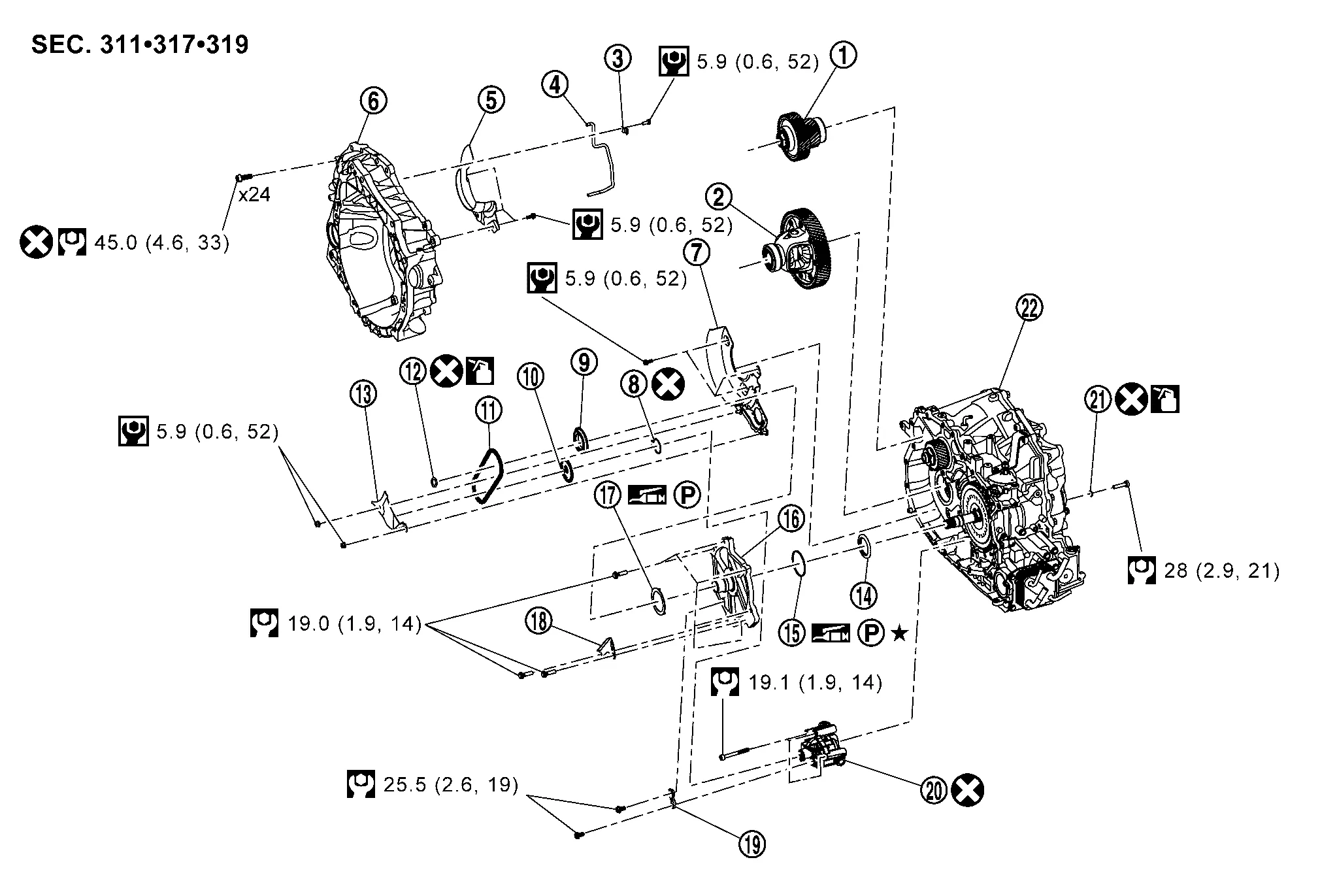
Reduction gear assembly |  |
Differential assembly |  |
Clip |
|
Lubrication tube | |
Baffle plate | |
Converter housing |
|
Baffle plate | |
Snap ring | |
Drive sprocket |
|
Driven sprocket | |
Oil pump chain | |
O-ring |
|
Baffle plate (Chain cover) | |
Thrust bearing | |
Thrust bearing race |
|
Dummy cover | |
Thrust washer |  |
Chain guide |
 |
Bracket |  |
Oil pump |  |
O-ring |
 |
Transaxle case | ||||
|
: Always replace after every disassembly. | ||||
|
: N·m (kg-m, ft-lb) | ||||
|
: N·m (kg-m, in-lb) | ||||
|
: Apply CVT fluid | ||||
|
: Apply petroleum jelly | ||||
 |
: Apply Liquid Gasket (loctite 5460) or equivalent | ||||
 |
: Select with proper thickness | ||||
|
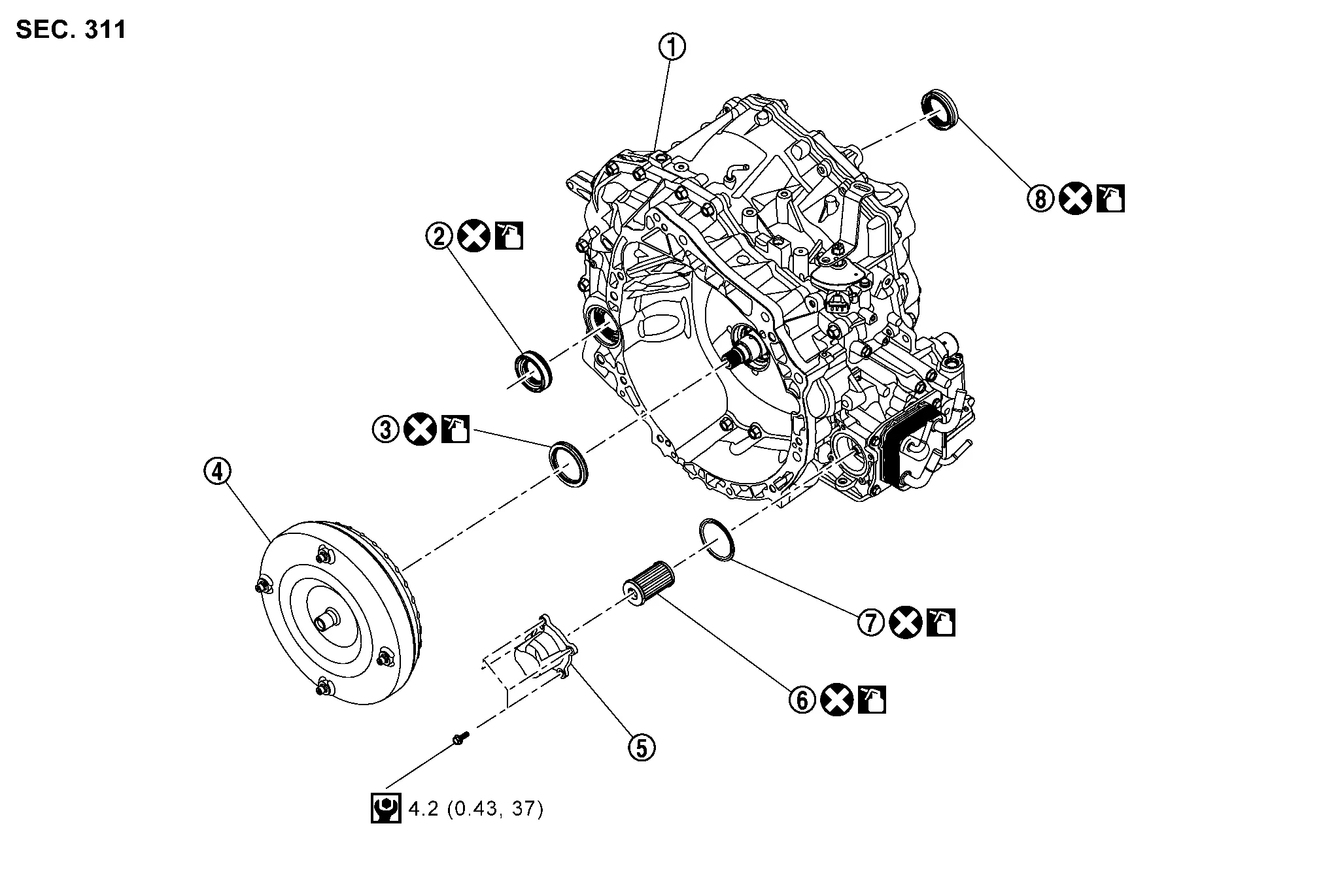
Transaxle assembly | |
Differential side oil seal | |
Converter housing oil seal |
|
Torque converter | |
Fluid filter cover | |
CVT fluid filter |
|
O-ring | |
Differential side oil seal | ||
|
: Always replace after every disassembly. | ||||
|
: N·m (kg-m, in-lb) | ||||
|
: Apply CVT fluid | ||||
|
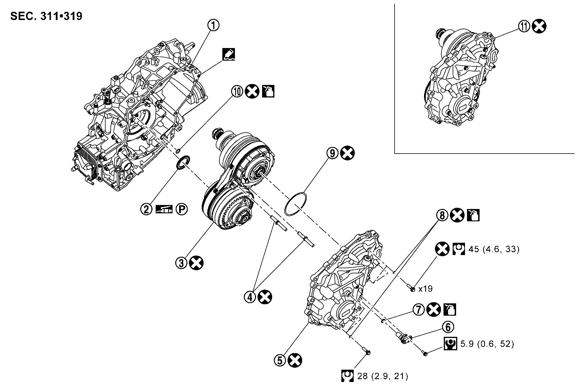
Transaxle case | |
Thrust bearing | |
Pulley bearings |
|
Lubrication cap | |
Side cover | |
Primary speed sensor |
|
O-ring | |
O-ring | |
Shim |
|
O-ring | |
Sub-assembly | ||
|
: Always replace after every disassembly. | ||||
|
: N·m (kg-m, ft-lb) | ||||
|
: N·m (kg-m, in-lb) | ||||
|
: Apply CVT fluid | ||||
|
: Apply petroleum jelly | ||||
|
: Apply Liquid Gasket (loctite 5460) or equivalent | ||||
CAUTION:
Perform the following items when replacing the control valve.
-
Check that the part number and serial number of the new control valve
are identical to those of the attached CD .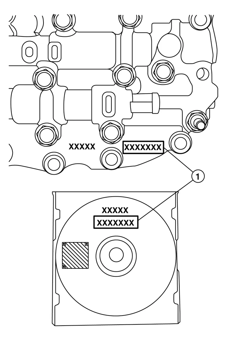
-
If old QR code sticker is affixed to transmission range switch, remove the QR code sticker and affix new QR code sticker included with new control valve.
 NOTE:
NOTE:
The CD provided with the new control valve contains important calibration data that must be installed with CONSULT after installation of the new control valve. Do not discard the CD.
Disconnect battery negative terminal.
Remove drain plug from oil pan and then drain the CVT fluid.
Remove drain plug gasket.
CAUTION:
Never reuse drain plug gasket.
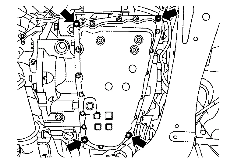
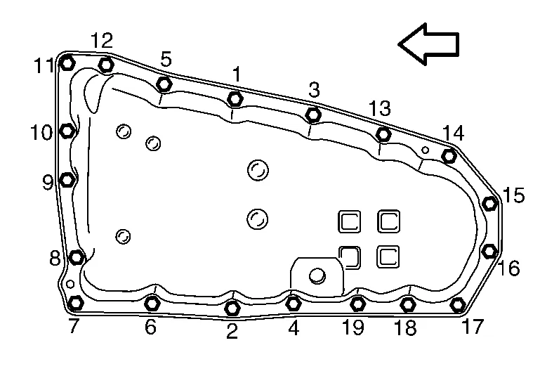
Remove the oil pan bolts, and then remove the oil pan and oil pan gasket.
CAUTION:
Never reuse oil pan gasket.
Remove the magnets from the oil pan.
NOTE:
Be sure to note the location of the magnets in the oil pan before removal.
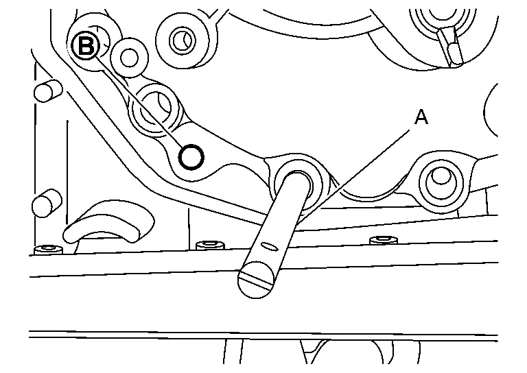
Remove the lock nut , spring washer , and manual plate from manual shaft  .
.
| : Front |
Remove the oil strainer assembly bolts and remove the oil strainer assembly.
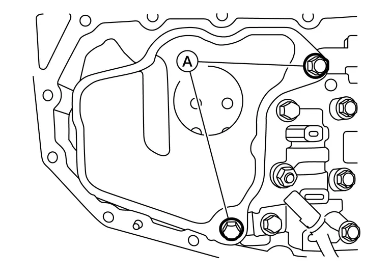
Remove CVT fluid temperature sensor bracket .
 |
: Bolt |
| : Front |
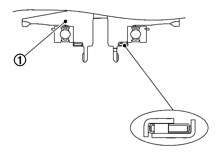
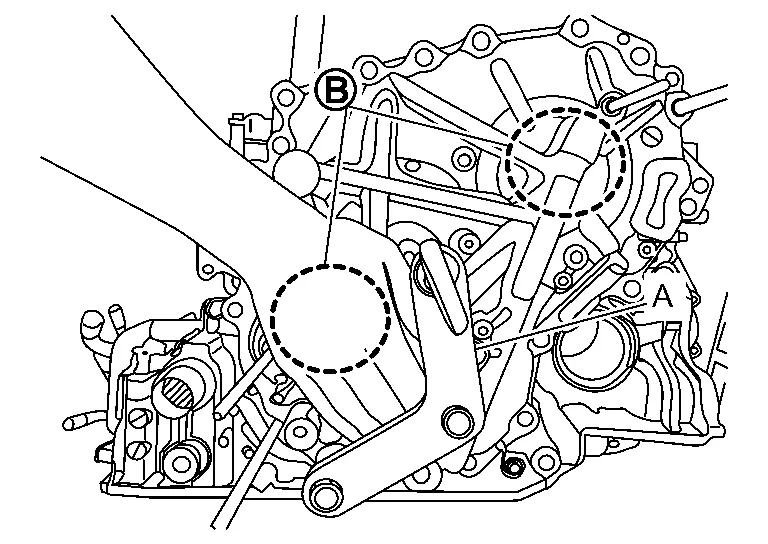
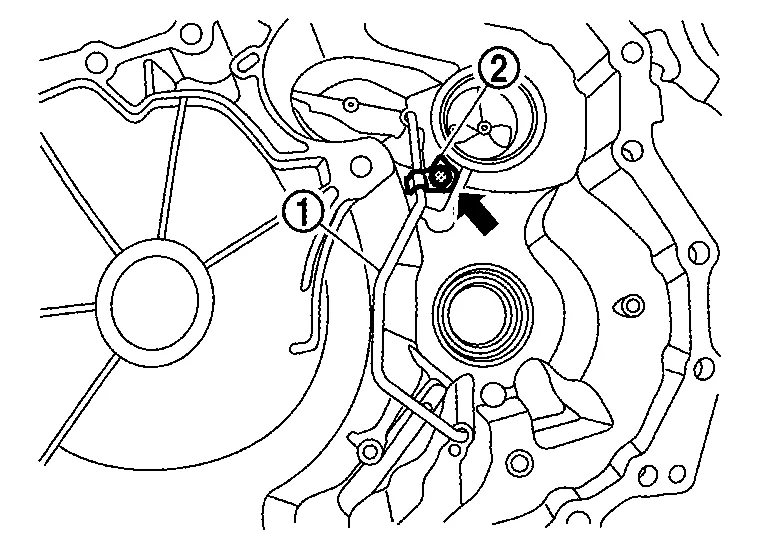
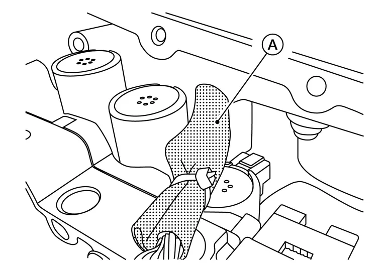
Disconnect control valve harness connector .
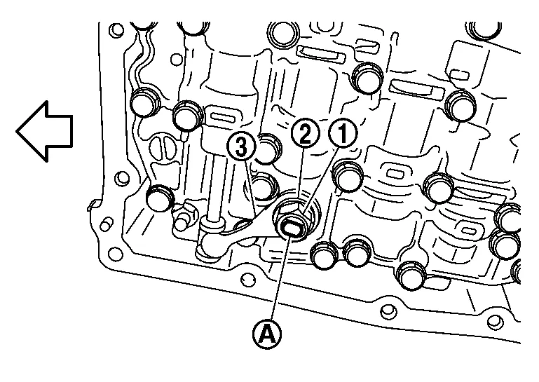
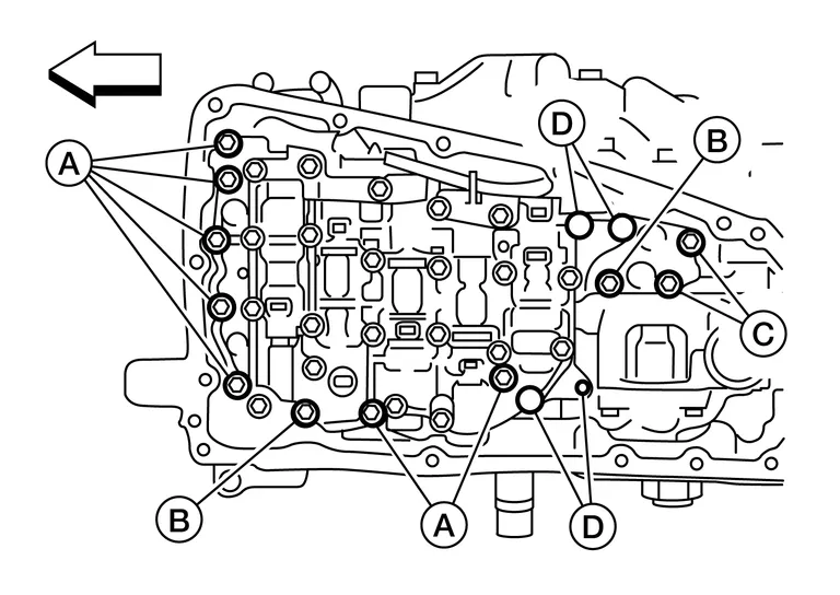
Remove the control valve bolts and  , and then remove the control valve from the transaxle case.
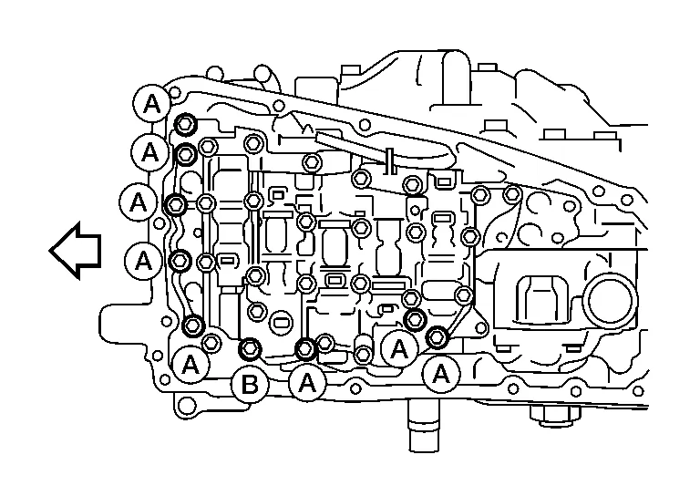
| : Front |
CAUTION:
Never drop the control valve, ratio control valve and manual shaft.
NOTE:
Control valve bolt heads may be marked with a number "7". Bolts marked as "7" are the bolts that need to be removed in order to remove the control valve.
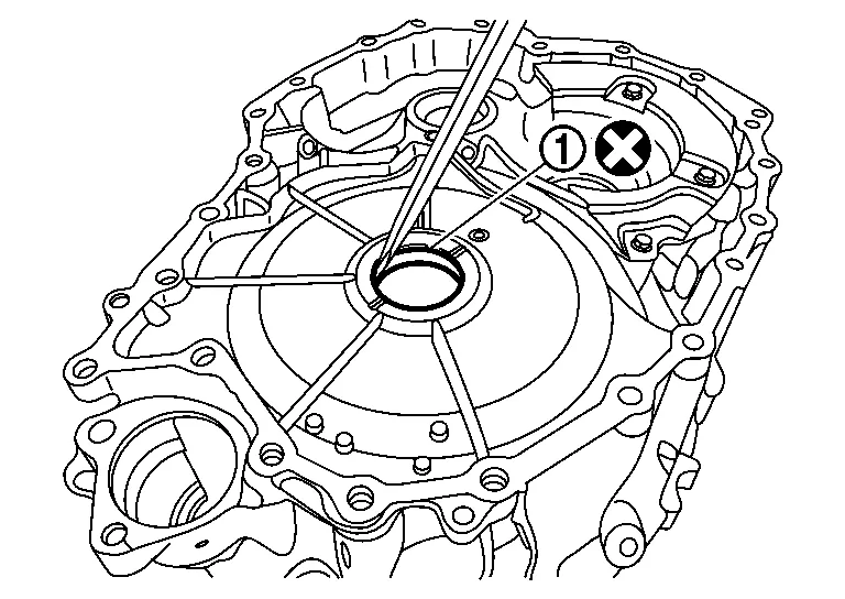
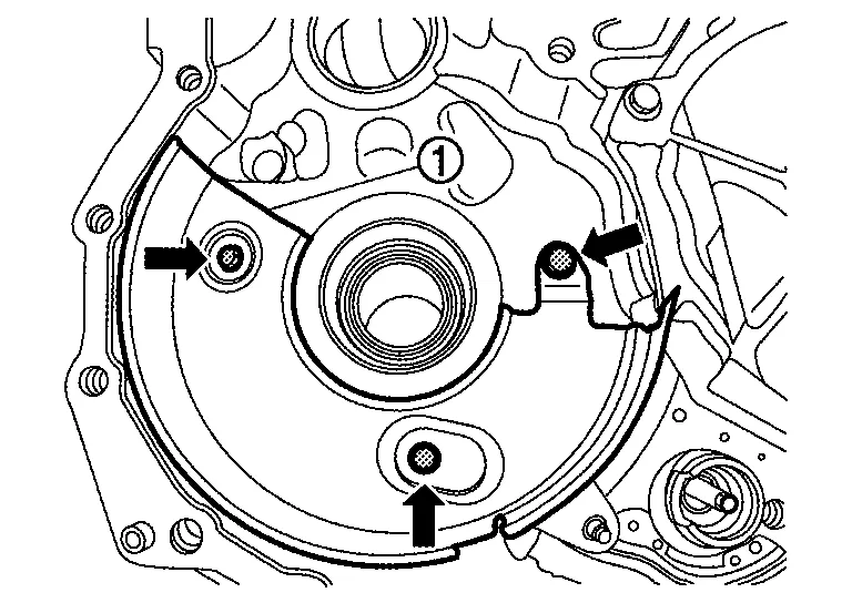
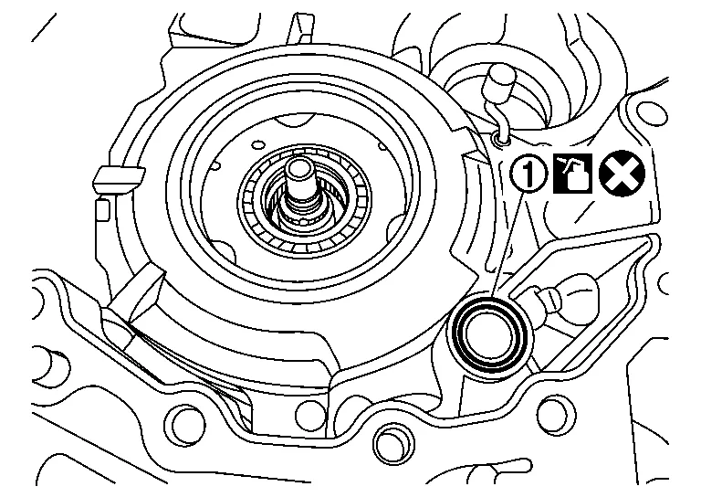
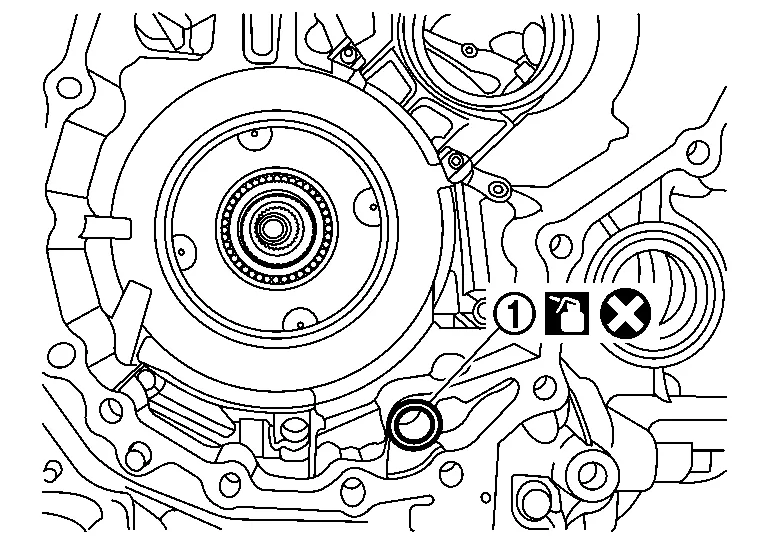
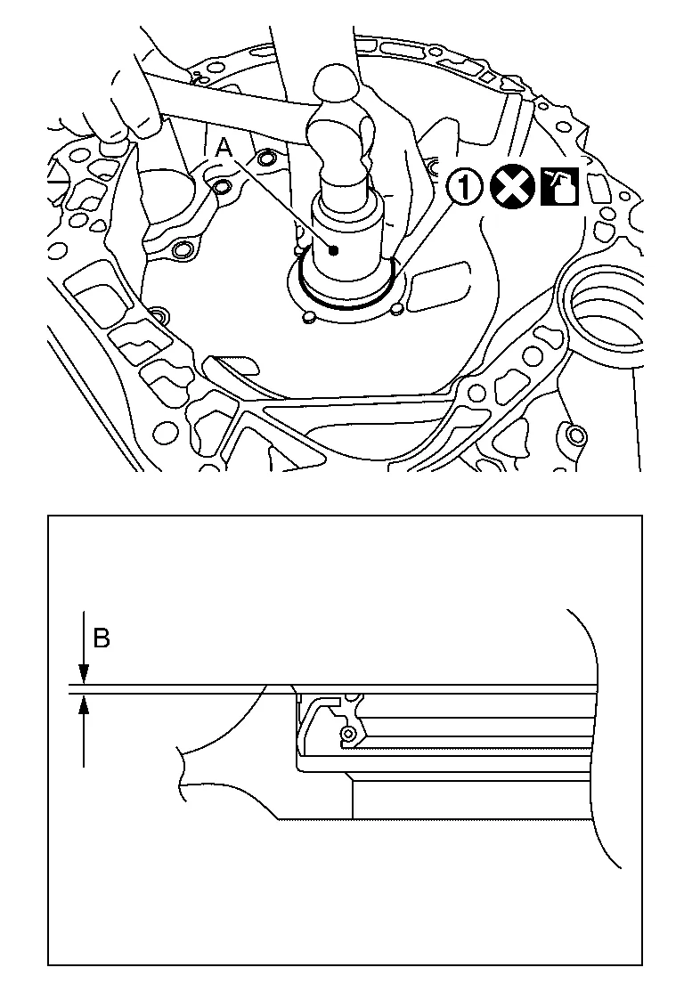
Remove the lip seal from the transaxle case.
CAUTION:
Never reuse lip seal.
| : Front |
Temporarily install the oil pan gasket and oil pan with four oil pan bolts (  ) to corners of the oil pan, hand tight.
NOTE:
It is not necessary for the control valve to be installed, a new one will be installed later in the service procedure.
Remove the CVT from the Nissan Murano vehicle. Refer to Removal and Installation - FWD (FWD) or Removal and Installation - AWD (AWD).
Mount the CVT on a workbench with the oil pan side down.
NOTE:
Use plastic or wood blocks to stabilize the CVT assembly on the work bench if needed.
CAUTION:
Be sure not to deform the oil pan.
Remove the torque converter .
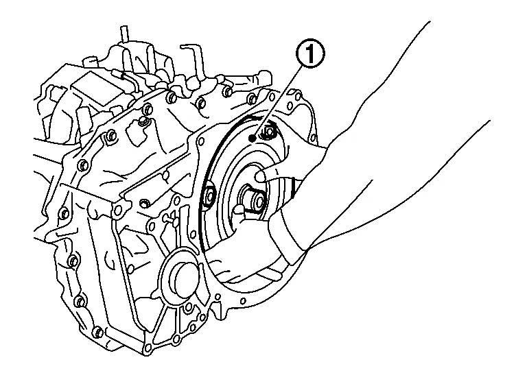
Drain the CVT fluid out of the torque converter .
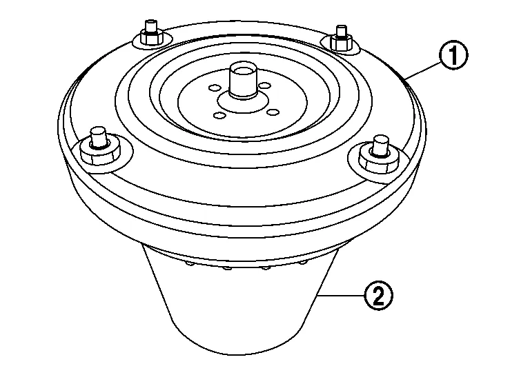
|
: Drain pan |
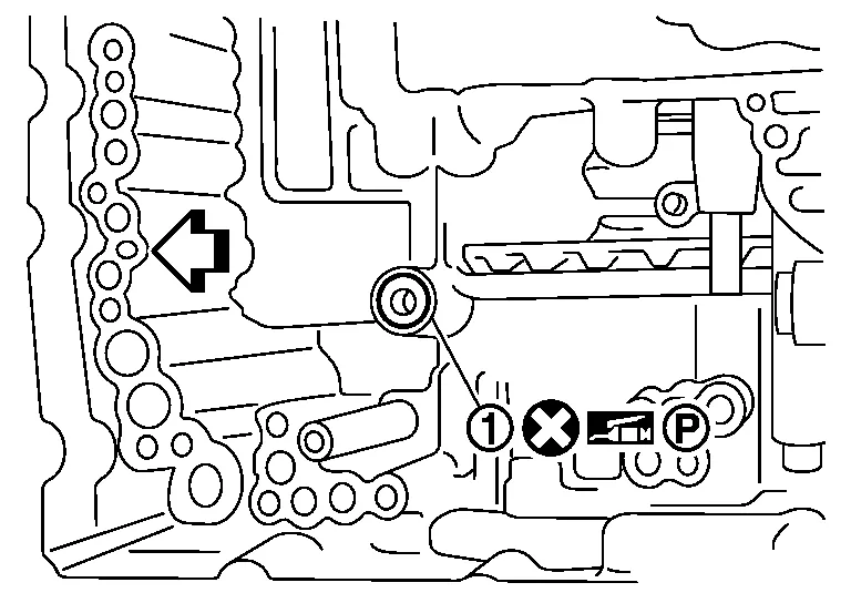
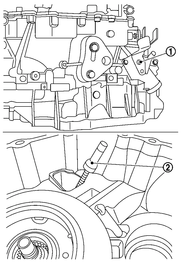
Remove mounting bolt () and remove primary speed sensor from transaxle assembly.
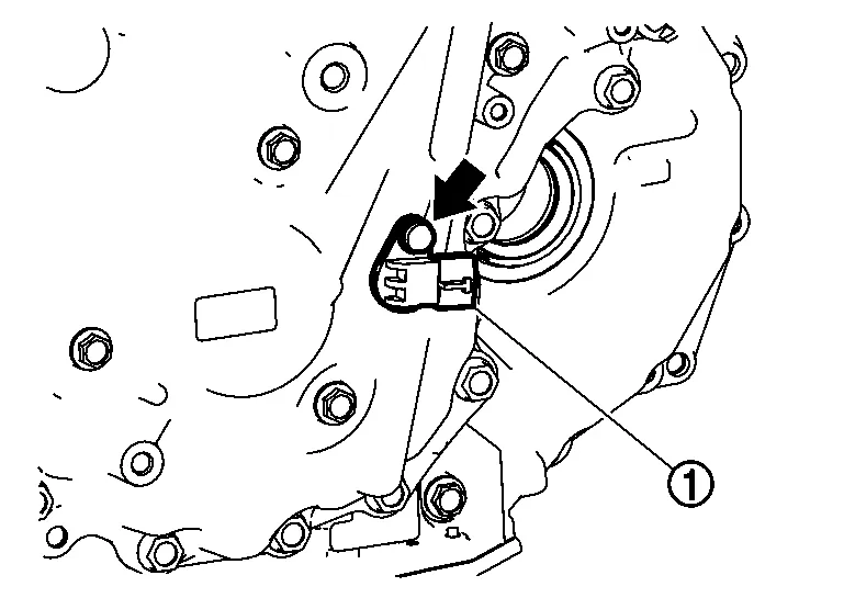
CAUTION:
Never impact the primary speed sensor when removing or installing primary speed sensor.
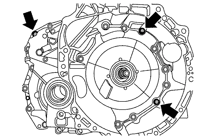
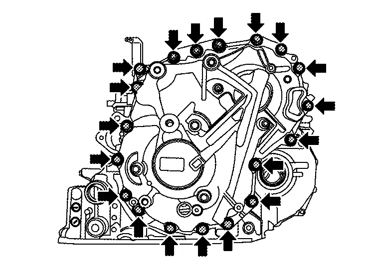
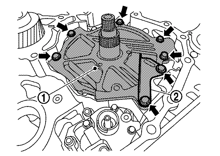
Remove the converter housing fixing bolts.
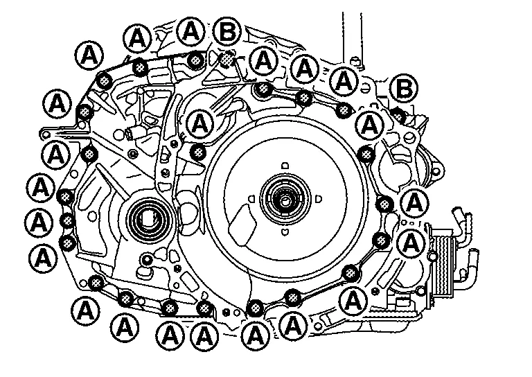
NOTE:
-
These bolts will be replaced with new ones and will not be reused.
-
Apply rust remover to the dowel pins if needed.
|
: Front bolts |
|
: Back side bolts |
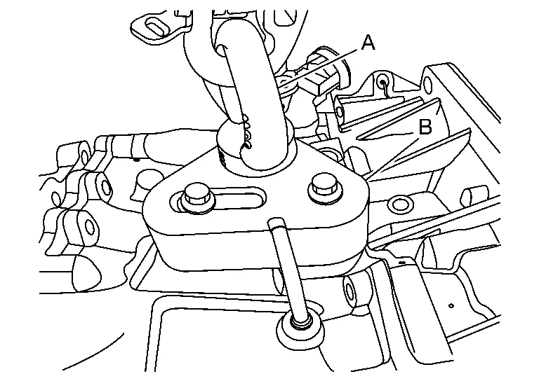
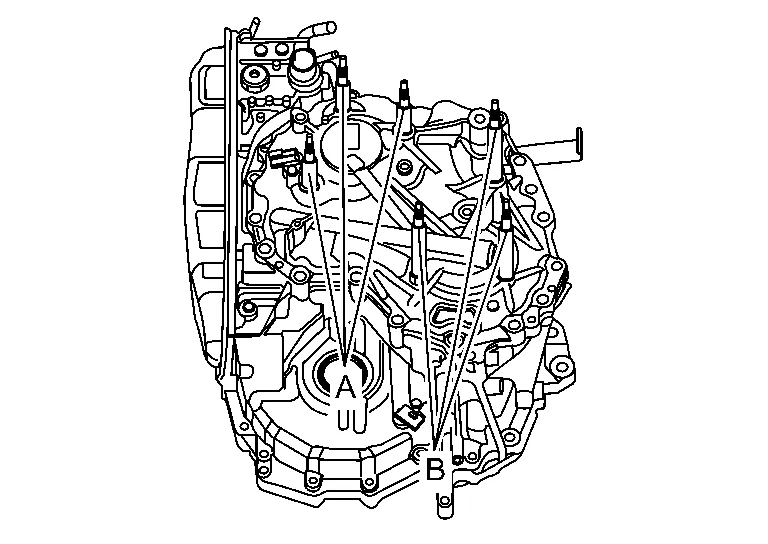
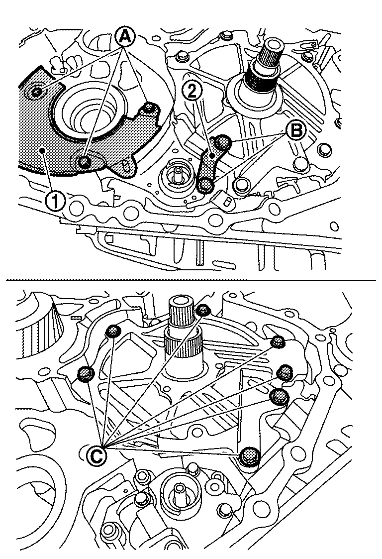
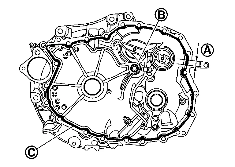
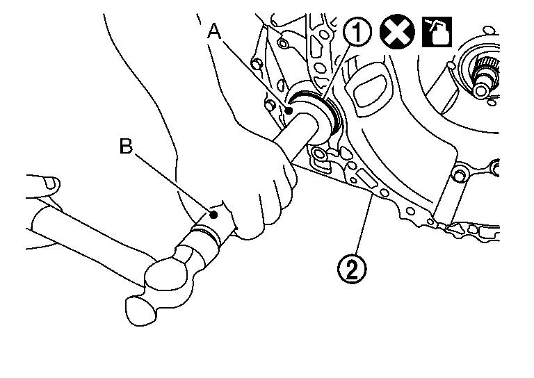
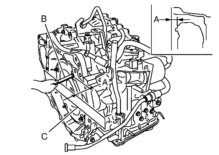
Separate and then remove the converter housing from the transaxle case. Use the slide hammer [SST: KV315J0610 (J-25721-A)] (A), slide hammer nut and bolt kit [SST: KV315J0630 (J-50255-UPD)] (B), and J-hook case separator [SST: KV315J0620 (J- 51923)] (C) at the cut out areas similar to the one shown in figure.
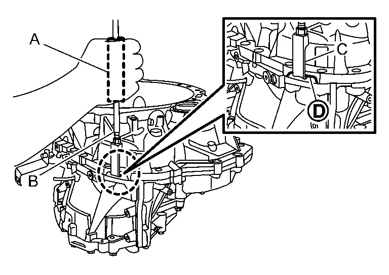
 |
: Cutout area (total 3 places) |
CAUTION:
Never use a pry-bar, chisel, etc. to separate the converter housing from the transaxle case.
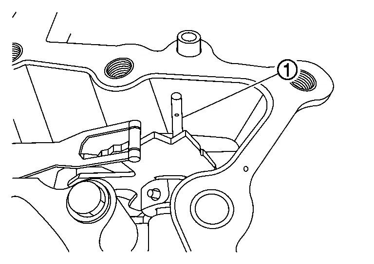
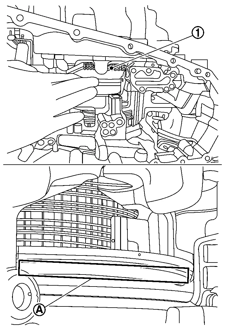
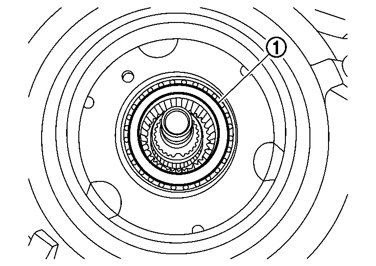
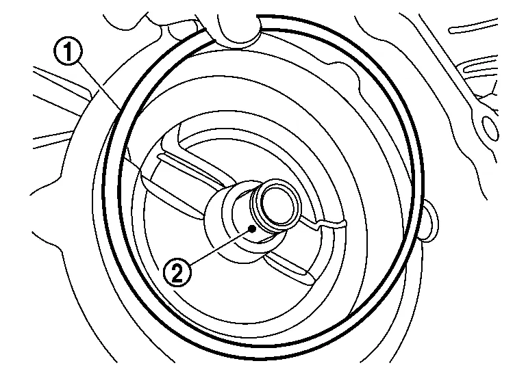
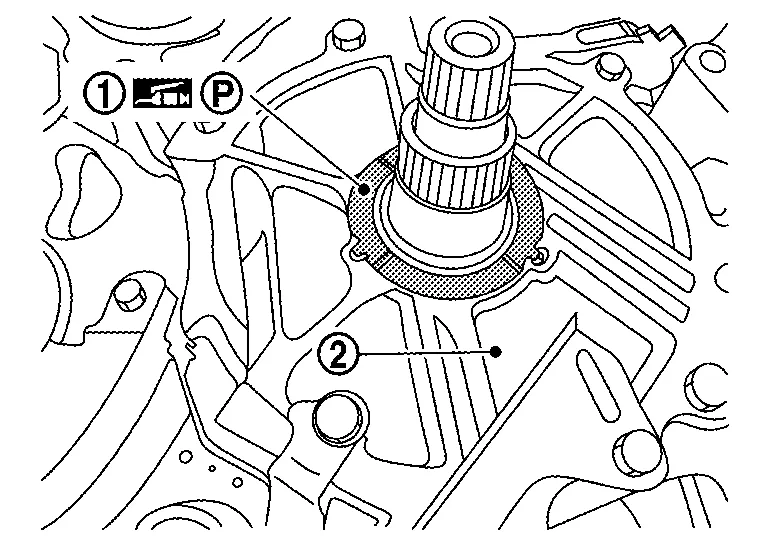
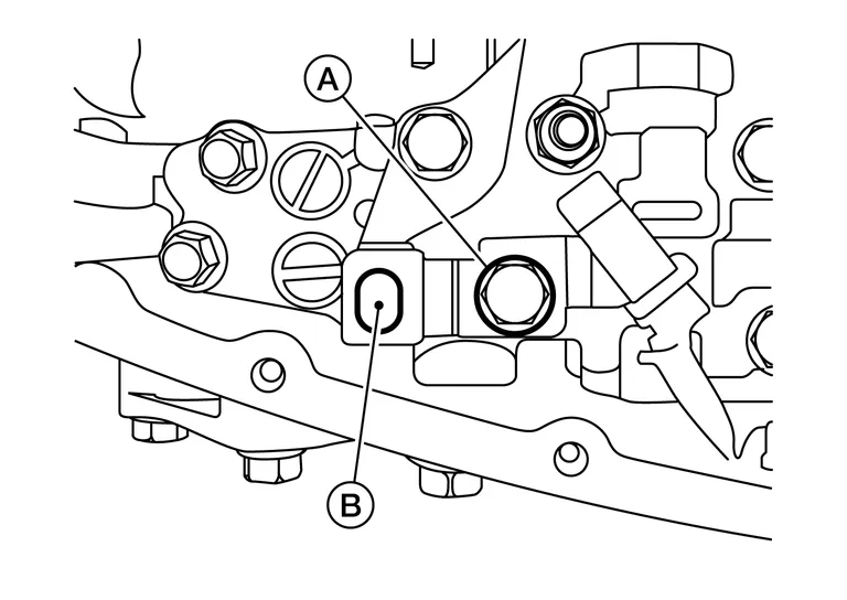
Check that retaining pin of manual shaft locates on the original position.
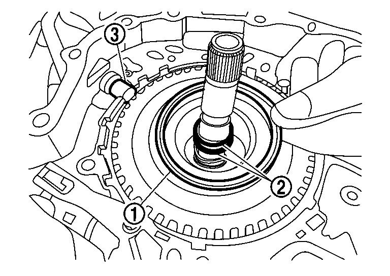
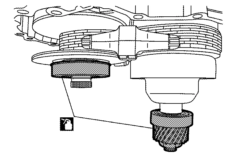
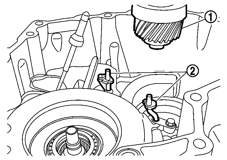
Remove the O-ring from the input shaft.
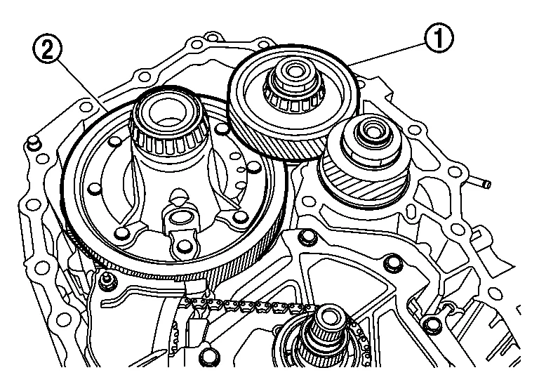
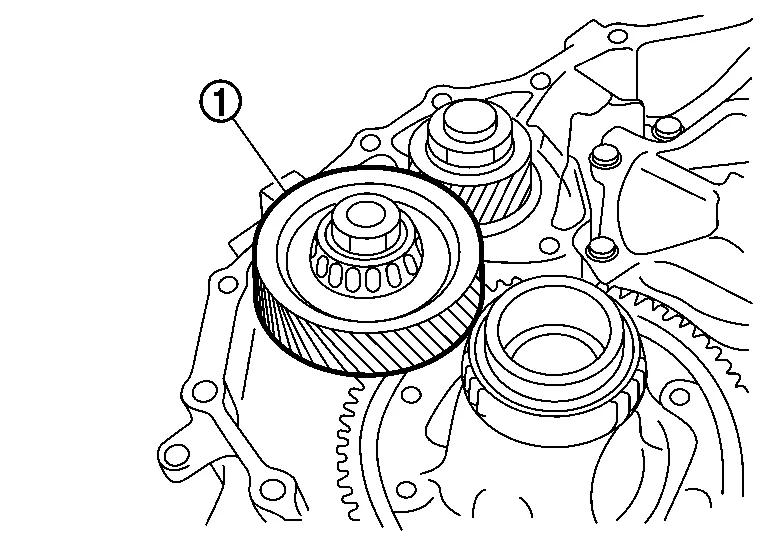
Carefully remove the reduction gear assembly and the differential assembly .
Remove the following oil seals using suitable tool:
CAUTION:
Be careful not to damage any of the seal bore surfaces.
-
Transaxle case differential side oil seal (drive shaft seal)
-
Torque converter seal
-
Converter housing differential side oil seal (drive shaft seal)
(FWD only)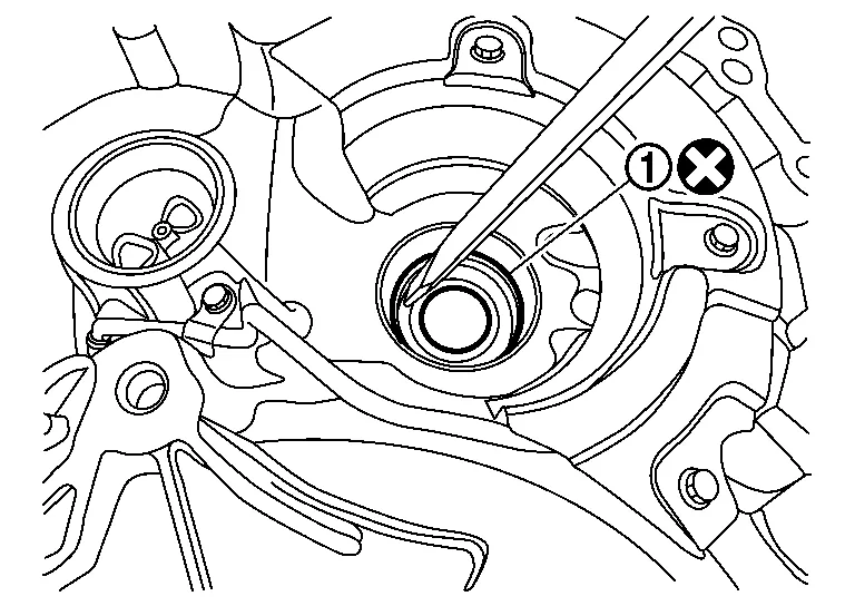
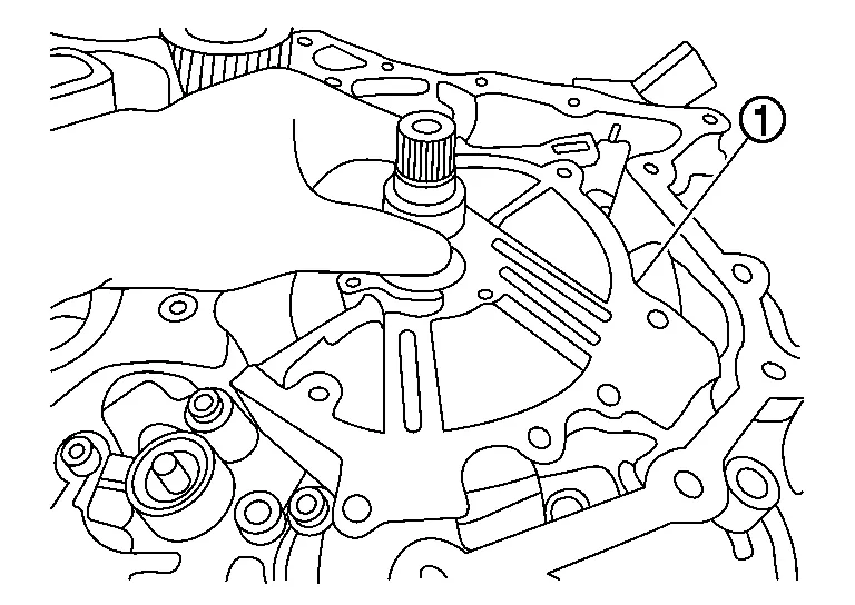
Remove the baffle plate (chain cover) .
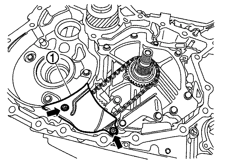
|
: Nut |
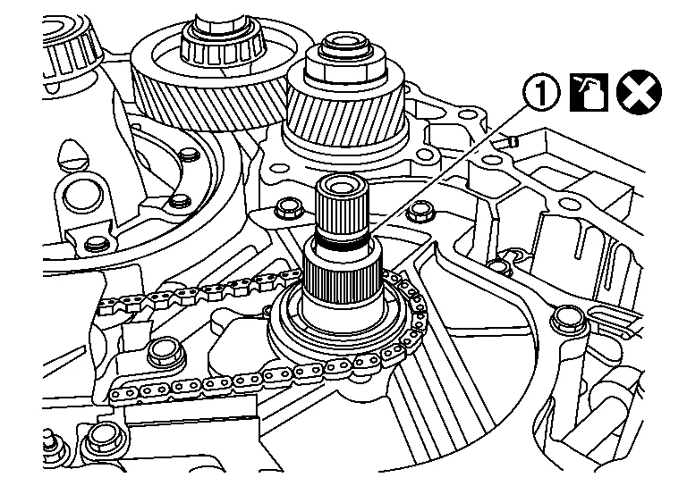
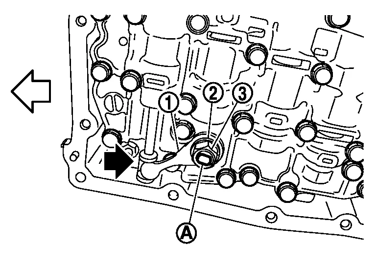
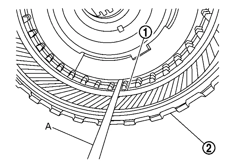
Remove the oil pump chain , driven sprocket and drive sprocket as one assembly in the following procedure.
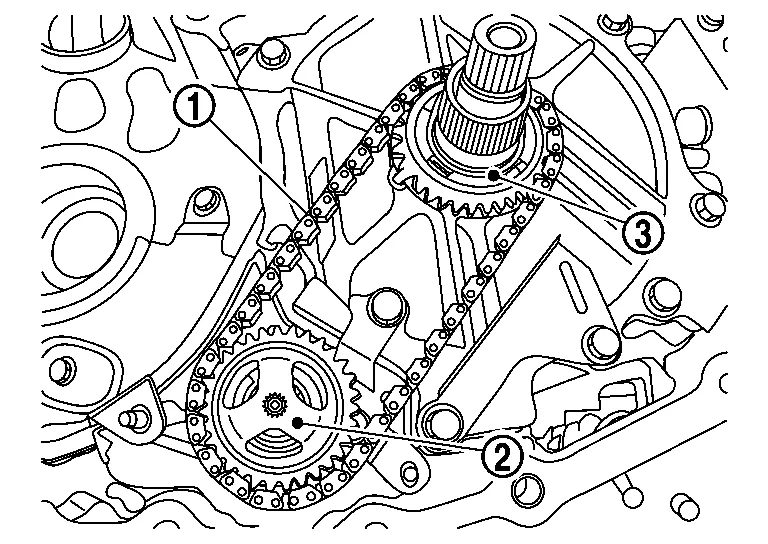
-
Spread the snap ring
using snap ring pliers.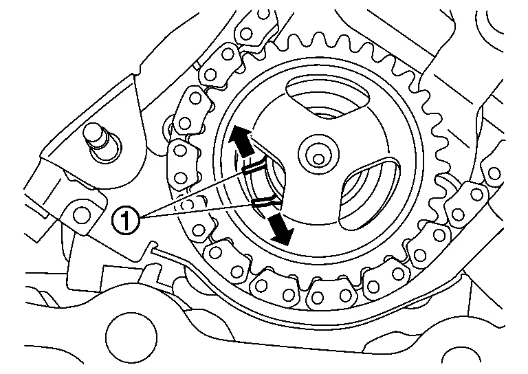
-
Lift the driven sprocket and the drive sprocket horizontally.
CAUTION:
The drive sprocket has a specific top and bottom. Keep the sprockets and chain together after they are removed.
Remove the thrust washer .
Remove the snap ring .
Remove the bracket .
|
: Bolt |
Remove the baffle plate .
|
: Bolt |
Remove the chain guide .
|
: Bolt |
Remove the dummy cover .
|
: Bolt |
CAUTION:
Never grasp the input shaft and lift it.
CAUTION:
Never remove the seal rings .
Remove the thrust bearing clutch assembly. And wipe any metallic debris off of the face of the secondary speed sensor .
CAUTION:
Be careful not to damage seal rings .
Remove the thrust bearing race from the dummy cover.
CAUTION:
Be careful not to damage seal rings .
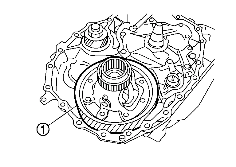
Remove the oil pump fixing bolts (4 pieces) and then remove the oil pump .
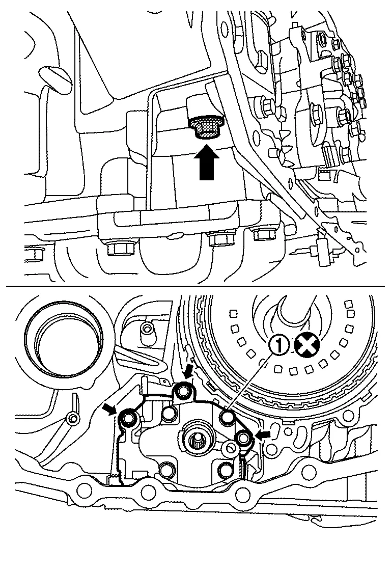
|
: Bolt |
Remove CVT fluid filter as follows:
-
Remove the bolts (
)and then remove the CVT fluid filter cover .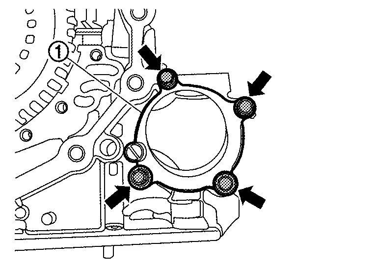
-
Remove the CVT fluid filter
with grommet seal and O-ring seal .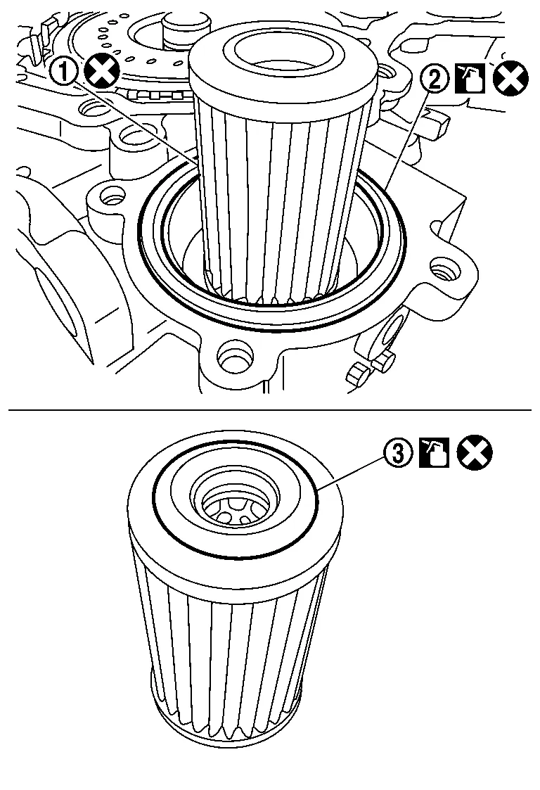
Thoroughly clean the mating surfaces of the transaxle case and torque converter housing.
NOTE:
A plastic scraper can be used.
CAUTION:
-
Never use sanding discs, similar abrasive tools, or metal blades.
-
Use parts cleaner or equivalent solvent and lint-free paper only.
-
Make sure the parts cleaner or solvents used are compatible with local regulations.
-
Prevent debris from entering in the CVT.
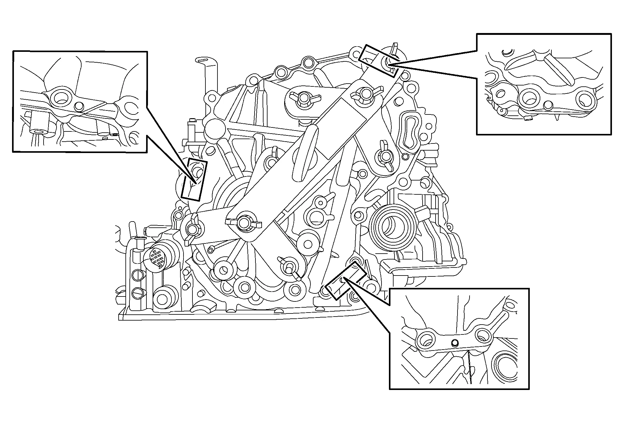
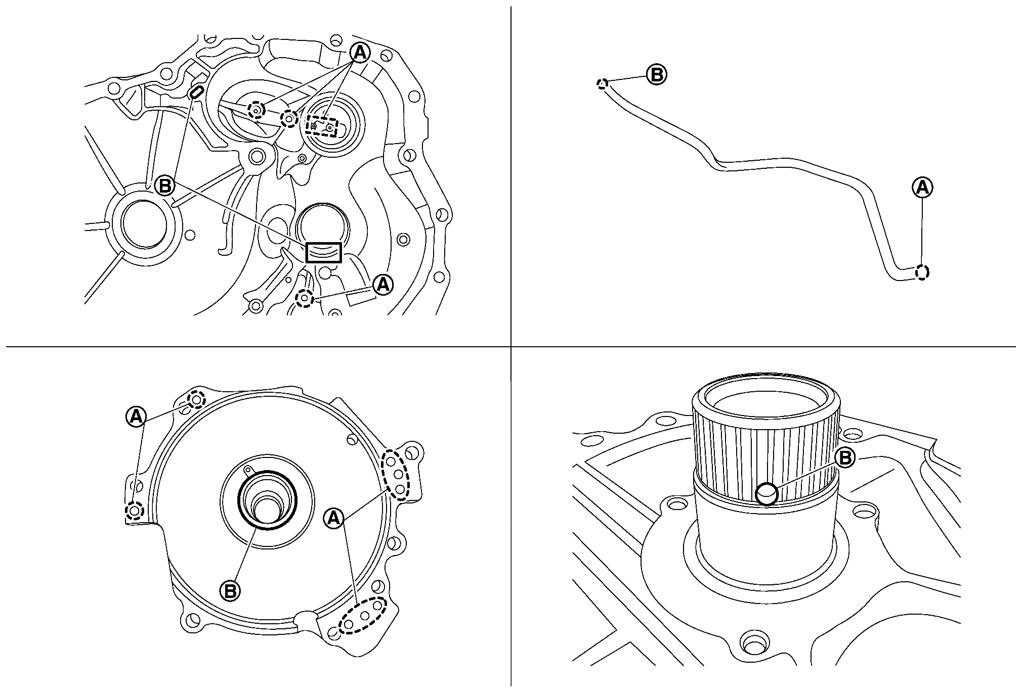
Make sure rust and debris have been cleaned off of dowel pins and receiving holes .
NOTE:
Use small wire brush or similar tool at the inside surface of dowel pin holes. Do not scrape transaxle case mating surfaces.
Clean the oil passages in the transaxle case, dummy cover, and CVT fluid filter area.
NOTE:
-
Parts cleaner or a suitable cleaning solvent and compressed air will be used to clean out fluid passages in the CVT assembly.
-
Make sure the parts cleaner or solvents are compatible with local regulations.
CAUTION:
-
Wear eye / face protection when using compressed air and cleaning fluids.
-
Regulate air pressure up to a maximum of 517 kpa (5.27 kg/cm2, 75 psi).
-
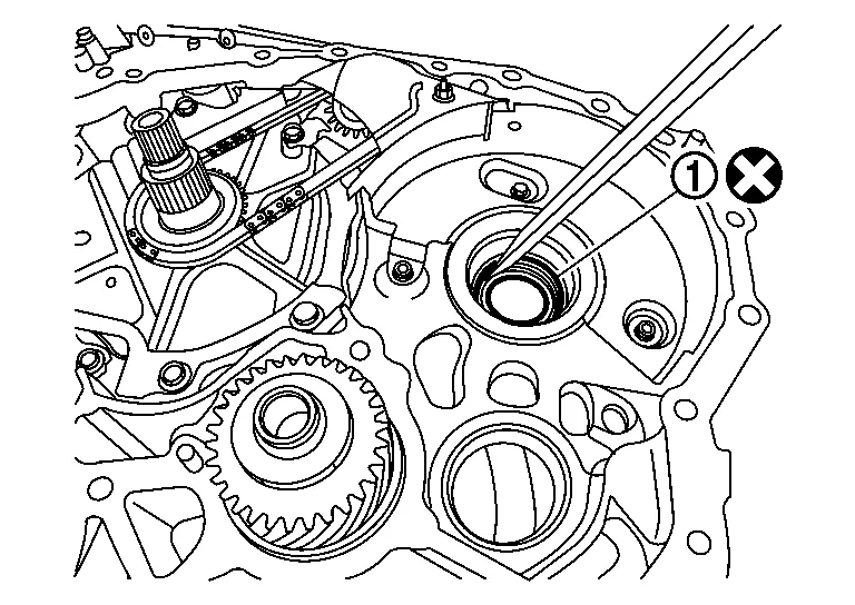
Clean the area where the CVT fluid filter fits
.NOTE:
Make sure the old filter grommet seal is removed.
-
Clean the fluid passages
to and from the filter.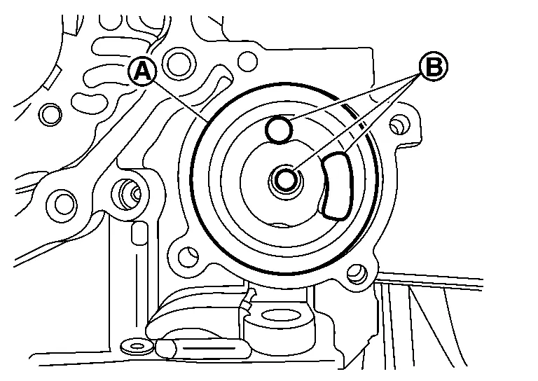
-
Spray parts cleaner in all fluid passages
of the transaxle case where shown in figure.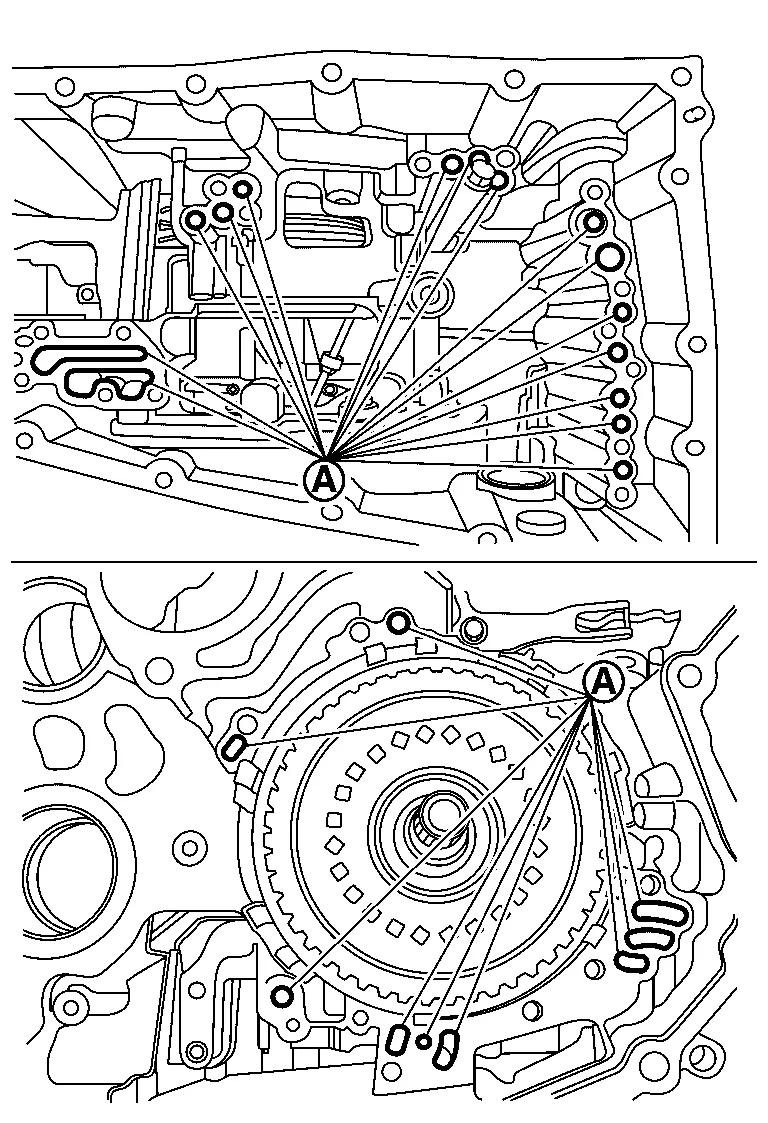
CAUTION:
Never spray parts cleaner into the clutch assembly.
-
Apply compressed air in the same passage.
CAUTION:
Never stand in front of the passages while using compressed air.
Temporarily install fluid filter cover.
Install the O-ring to the oil pump mounting bolts. (Only for the bolt installed from the outside of the transaxle case)
CAUTION:
-
Never reuse the O-ring.
-
Apply the CVT fluid to the O-ring.
Install the oil pump on the transaxle case and tighten the mounting bolts to the specified torque. (One of the oil pump retaining bolts is installed from the outside of the transaxle case in the rear part of the oil pump.)
|
: Bolt |
CAUTION:
Never reuse the oil pump.
Install the snap ring .
CAUTION:
Never reuse the oil pump snap ring.
Temporarily install the dummy cover with 3 bolts ( ).
CAUTION:
-
Never install the thrust bearing to the clutch assembly bore at this time.
-
If cover does not seat flush, refer to Trouble Shooting.
Temporarily install the converter housing onto the transaxle case with 3 bolts ( ).
CAUTION:
When fitting the CVT case surfaces, never use the bolts to draw in the case halves. Make sure the case surfaces are flush, and have no gaps prior to installing the bolts.
Reposition the CVT assembly on the work bench with the side cover side facing up.
NOTE:
-
CVT lifter bracket (SST: J-51595) (B) and CVT lifting eye/swivel assembly (SST: J-51595- 1) (A) can be used for this step.
-
Use plastic or wood blocks to stabilize the CVT assembly on the work bench if needed.
CAUTION:
-
Never hit the manual shaft
while repositioning the CVT; the manual shaft is longer than the oil pan mating surface.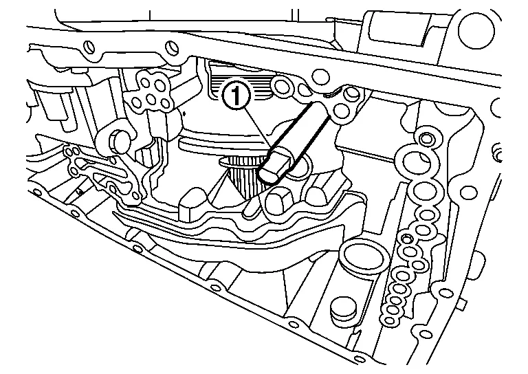
-
Never pinch the terminal connector harness between the transaxle case and work bench or supporting block.
Rotate the primary pulley by hand to check the pulley’s rotational characteristics.
CAUTION:
Never place fingers between the pulley and the transaxle case .
NOTE:
Remember the pulley’s rotational characteristics. This will be used as a reference after the new side cover-pulleys and belt sub-assembly (sub-assembly) have been installed.
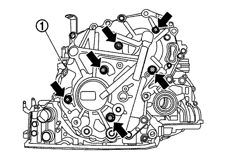
Remove the side cover fixing bolts.
|
: Bolt |
NOTE:
When working with sub-assembly install, uninstall, and bracket attachment, it is critical that CVT and sub-assembly are level.
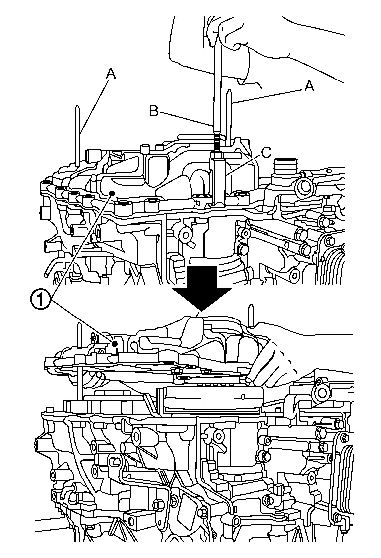
Attach the CVT universal lifting fixture [SST: KV315J0100 (J–52082)] (B) with spacers (SST: J–52082–2) (A) to the side cover.
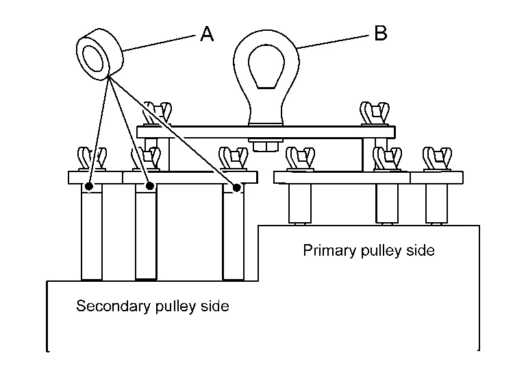
NOTE:
Tighten the wing-nut bolts on the CVT universal lifting fixture [SST: KV315J0100 (J-52082)] finger tight in the following order:
-
Remove the pulley bracket bolts (
) from side cover .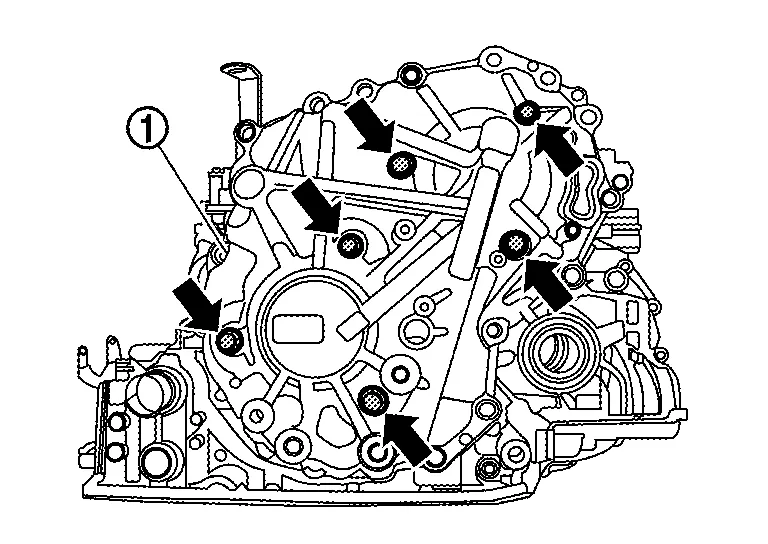
-
Install medium (A) and long (B) shafts of CVT universal lifting fixture [SST: KV315J0100 (J-52082)].
-
Install spacers (SST: J-52082-2) (A) and CVT universal lifting fixture [SST: KV315J0100 (J-52082)] (B) to shafts.
CAUTION:
Install CVT universal lifting (A) properly.
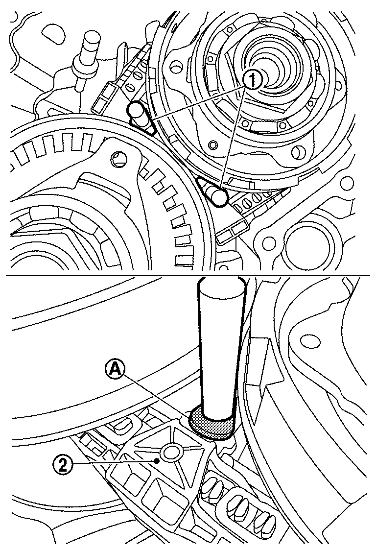
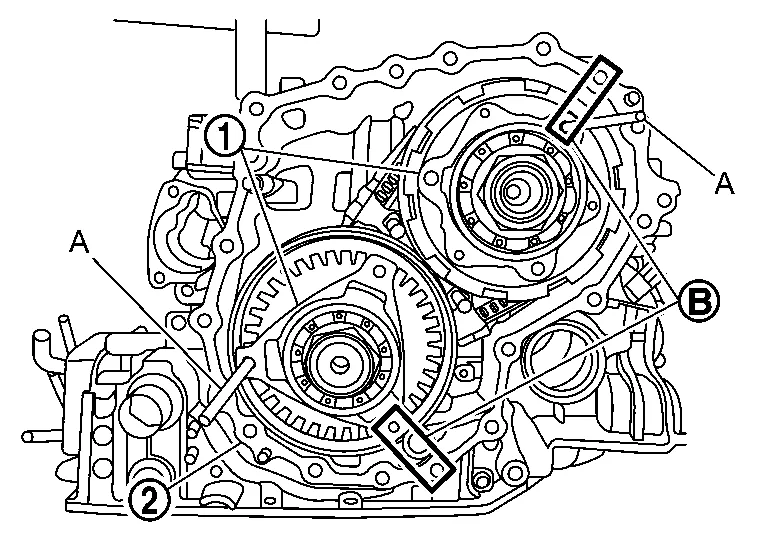
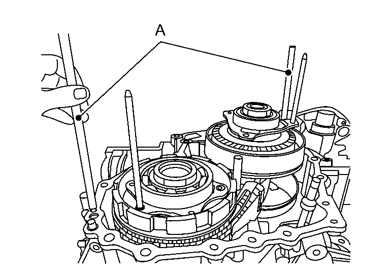
Attach the CVT assembly guide pins [SST: KV315J0200 (J-51959)] (A) as shown in figure.
NOTE:
Guide pins must be placed next to dowel pins ,
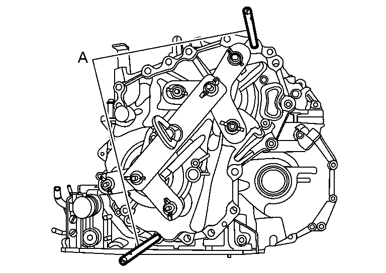
Lift up the CVT universal lifting fixture [SST: KV315J0100 (J-52082)] so that the CVT assembly weight is mostly supported by the CVT universal lifting fixture and just slightly raised off of the work surface.
Loosen the side cover with a slide hammer at the three points.
CAUTION:
Never use a pry-bar, chisel, etc. to separate the side cover from the transaxle case.
NOTE:
Apply rust penetrant to the two dowel pins as needed.
Lift up the CVT universal lifting fixture [SST: KV315J0100 (J-52082 )] to remove the sub-assembly from the transaxle case.
Remove the CVT universal lifting fixture from the sub-assembly.
NOTE:
Check that dowel pins have remained in the transaxle case. If not, remove dowel pins from the sub-assembly and relocate back to the transaxle case.
Thoroughly clean the mating surfaces of the CVT case that the subassembly was just separated from.
CAUTION:
-
Never use sanding discs, similar abrasive tools, or metal blades.
-
Use parts cleaner or equivalent solvent and lint-free paper only.
-
Make sure the parts cleaner or solvents used are compatible with local regulations.
-
Prevent debris from entering in the CVT.
-
Make sure rust and debris have been cleaned off of dowel pins and receiving holes.
-
Use small wire brush or similar tool at the inside surface of dowel pin holes. Do not scrape transaxle case mating surfaces.
NOTE:
The CVT assembly guide pins [SST: KV315J0200 (J-51959)] can be temporarily removed for cleaning purposes.
Replace the O-ring .
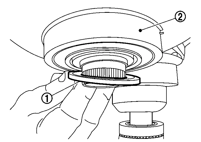
Remove the thrust bearing from the planetary carrier assembly.
NOTE:
If not found on the planetary carrier assembly, the thrust bearing may still be attached to the primary pulley.
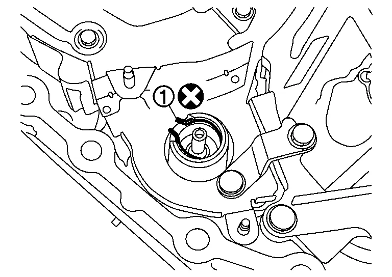
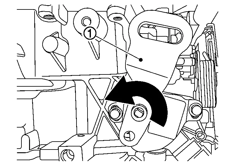
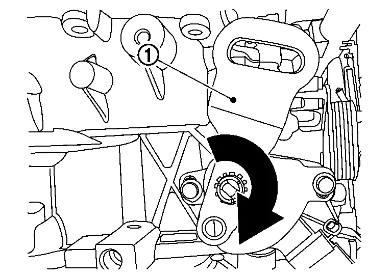
Rotate the shift select lever clockwise on the side of the CVT to adjust the parking rod to the lowest position.
Remove the pulley bracket bolts ( ) from the side cover of the new sub-assembly.
CAUTION:
Never reuse O-rings.
Attach the appropriate CVT universal lifting fixture [SST: KV315J0100 (J-52082)] (A) to the new sub-assembly, and then lift up sub-assembly out of the shipping box.
Install the original thrust bearing on the primary pulley of the new sub-assembly.
CAUTION:
-
Pay close attention to the direction of the needle bearing when installing.
: Primary pulley -
Apply a small amount of petroleum jelly or equivalent to the original thrust bearing to hold it in place on the primary pulley.
Apply CVT fluid to the primary pulley bearing, secondary pulley gear teeth and the secondary bearing when installing the new sub-assembly.
CAUTION:
Never drip any CVT fluid onto the sealant.
Attach the CVT assembly guide pins [SST: KV315J0200 (J-51959)] (A) to transaxle case when installing the new sub-assembly.
NOTE:
Guide pins must be installed next to dowel pins .
Install the the new sub-assembly to transaxle case.
CAUTION:
-
Never allow the output gear
to hit the lubrication tube when the side cover is positioned over the guide pins.
-
In the following steps be careful not to contact or contaminate the sealant.
-
Never use hammer when installing the new sub-assembly.
NOTE:
-
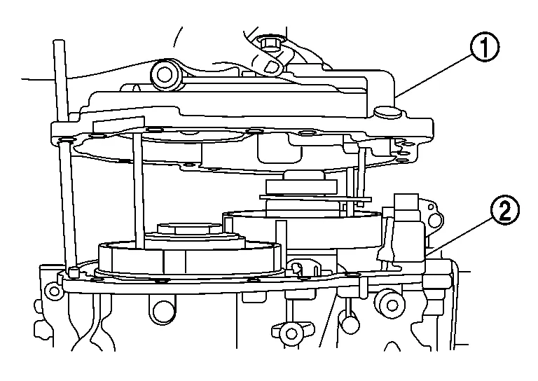
If the sub-assembly does not lower completely, physical interference is present. Check the “visual gap size
” below , between the sub-assembly and the transaxle case, to determine the cause of interference.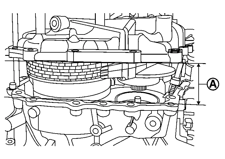
-
Sub-assembly
can not lower past 50 mm (1.97 inch). (Interference is present between the output gear and bearing bore .)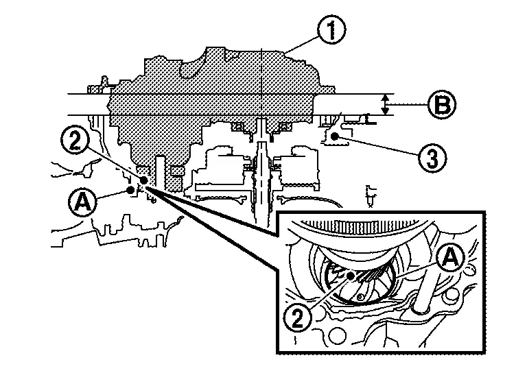
: Transaxle case : Case gap -
Sub-assembly can not lower past 40 mm (1.57 inch).
-
When installing side cover, insert parking rod
to parking pawl area .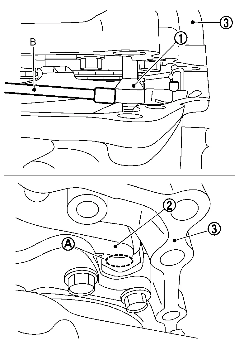
-
Install the parking rod into the parking pawl of the side cover with the following procedure.
-
Rotate the shift select lever clockwise on the side of the CVT to adjust the park rod
to the highest position. -
Use a magnet (B), or similar tool, to align the park rod
in the CVT case with the opening in the parking pawl in the side cover.: Side cover
-
-
-
Sub-assembly
can not lower past 18 mm (0.71 inch). (Primary and the secondary pulley bearings do not align properly with their bores or are at an angle.)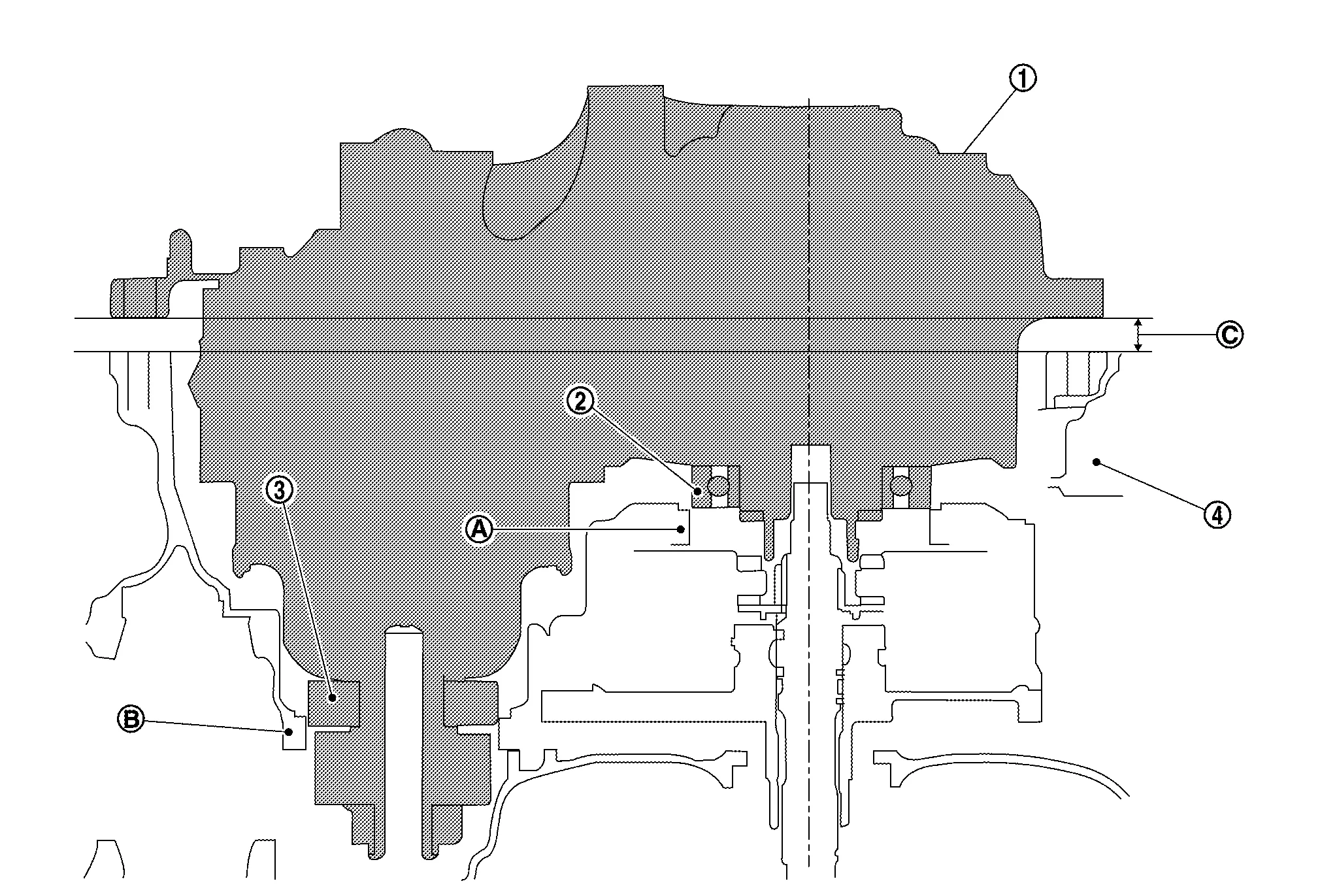
: Primary pulley bearing : Secondary pulley bearing : Transaxle case : Primary pulley bearing bore : Secondary pulley bearing bore 
: Case gap CAUTION:
-
If this occurs, never force sub-assembly into case.
-
Level the sub-assembly (visually check the gap between case and sub-assembly side cover and confirm that it is even all around).
-
-
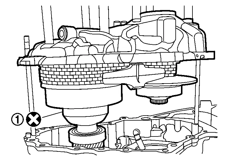
Sub-assembly ① can not lower past 5 mm (0.20 inch). (Primary pulley splines are not aligned.)
: Transaxle case : Primary pulley splines : Planetary carrier splines : Case gap CAUTION:
-
Never place fingers below primary pulley.
-
Be careful not to get fingers caught between the transaxle case and sub-assembly when seating.
-
If this occurs, never force sub-assembly into case.
-
Lift up the sub-assembly slightly so the weight is not completely on the primary pulley splines.
-
Check the dowel pins are clean and aligned and are not catching on the subassembly case cover.
-
Rotate the shift select lever to “N” range.
Remove the CVT universal lifting fixture from the side cover.
Remove the side cover as following procedure.
CAUTION:
-
Only slide hammer and hands to separate side cover.
-
Never use side cover alignment aid (SST: J-52275) at this step.
-
Attach the assembly guide pins, pulley bracket [SST: KV315J0300 (J-52272)] (A) to side cover.
-
Use slide hammer [SST: KV315J0610 (J-25721-A)] (B) with J-hook case separator [SST: KV315J0620 (J-51923)] (C) and evenly separate the side cover from the belt and pulley assembly.
-
Lift up the side cover by hand.
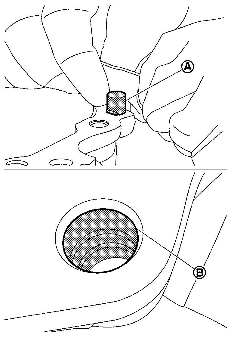
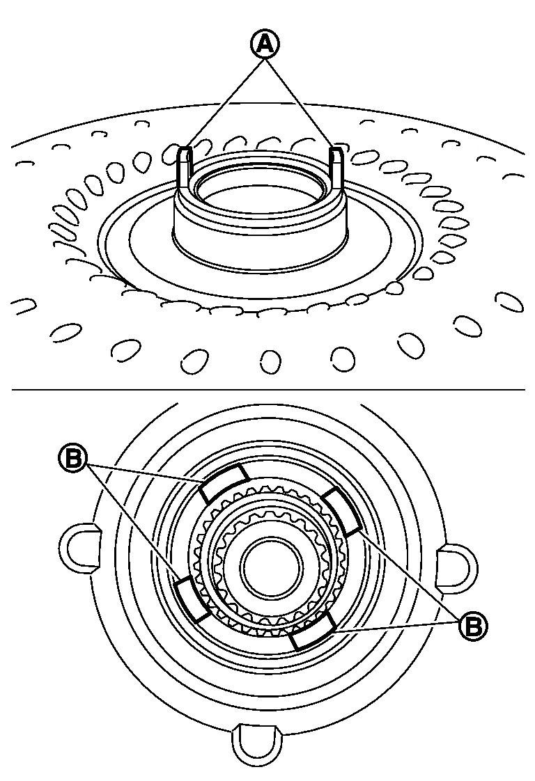
Install new lubrication caps onto the lubrication tubes.
NOTE:
-
Insert the lubrication caps through the slots in each chain guide
. -
Face the larger side of the wedge shaped index guide (A) away from the pulleys.
Rotate each pulley bracket to align with holes and assembly guide pins, pulley bracket [SST: KV31500300 (J-52272)] (A) in the transaxle case .
|
: Align holes |
Install a new O-ring .
CAUTION:
-
Never reuse the O-ring.
-
Apply the CVT fluid to the O-ring.
Check that the shim and the seal ring , on the underside of the side cover.
NOTE:
Apply petroleum jelly as needed to keep the shim and seal ring in place while lowering the side cover to the transaxle case.
Attach the side cover alignment aid (SST: J-52275) (A) to side cover .
NOTE:
The alignment aid will assist with level installation and help keep integrity of sealant.
Lift up side cover and check that the underside case mating surface is clean.
Apply Loctite 5460 on the transaxle case installation surface of the sub-assembly.
CAUTION:
-
Confirm that the mating surfaces are clean before applying sealant.
-
The sealant width is 2.0 mm (0.08 in).
-
Check that the starting point and the ending point are about the middle between the bolts. The overlap both ends of the bead by 3 - 5 mm (0.12 - 0.20 in)
.
-
Be careful not to contact or contaminate the sealant. If the sealant has been disturbed or contaminated in any way before case assembly, thoroughly clean the mating surfaces of the transaxle case and re-start from step 74.
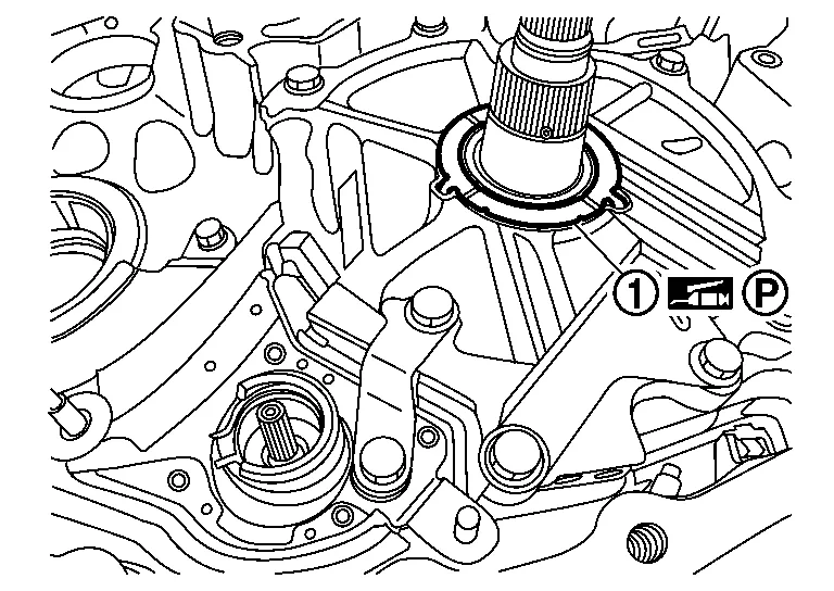
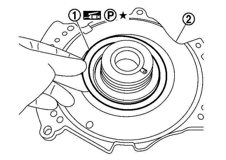
Rotate the shift select lever clockwise to the “P” range to set the parking rod at the highest position.
Attach the CVT assembly guide pins [SST: KV315J0200 (J-51959)] (A).
Install the side cover to the transaxle case .
CAUTION:
-
Never use hammer when installing the side cover.
NOTE:
-
Keep the side cover as level as possible during installation.
-
When installing side cover, insert parking rod
to parking pawl area .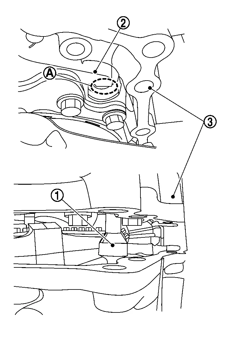
: Side cover -
Lower the side cover until the parking rod can be aligned with parking pawl.
-
Perform following step while the side cover has a 38 mm gap (1.5 inch) to the transaxle case.
-
Rotate the shift select lever clockwise on the side of the CVT to adjust the park rod
to the highest position. -
Use a magnet, or similar tool, to align the park rod in the CVT case with the opening in the parking pawl
in the side cover.
-
By hand, press down on the side cover over each of the pulley bearings to level and seat the side cover.
| A | : Side cover alignment aid (SST: J-52275) |
|
: Pressure area |
NOTE:
The side cover will not be fully seated at this step.
Rotate the shift select lever to the “N” position.
Remove the side cover alignment aid (SST: J-52275).
Continue to lower the side cover fixed transaxle case.
NOTE:
Use a plastic hammer or rubber mallet, if the side cover is caught, and gently tap evenly around the top of the side cover to help seat.
CAUTION:
-
Never use metal hammers or mallets.
-
If it is necessary to unseat the side cover assembly, use a slide hammer and then restart from step 72.
Remove the CVT assembly guide pins [SST: KV315J0200 (J-51959)].
NOTE:
Leave the assembly guide pins, pulley bracket [SST: KV31500300 (J-52272)] in place.
Install the new side cover bolts and temporary tighten them. And then, tighten the bolts to specified torque in the order shown.
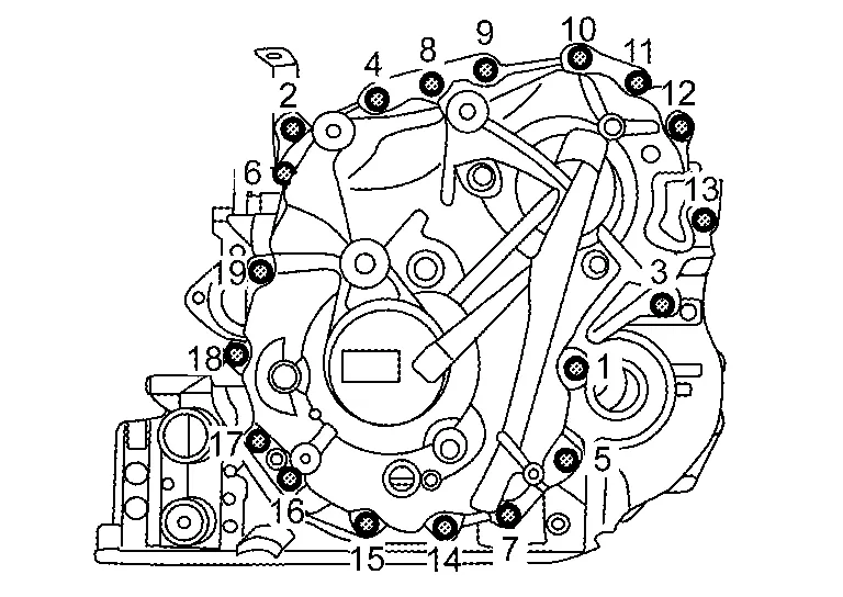
CAUTION:
Never reuse the side cover bolts.
Install the new pulley bracket bolts with new O-rings ( ) to side cover as following procedure.
-
Install four bolts with O-rings first, hand tight.
CAUTION:
-
Never reuse the pulley bracket bolts and the O-rings.
-
Apply the CVT fluid to the O-rings.
-
-
Remove the assembly guide pins, pulley bracket [SST: KV31500300 (J-52272)] from the pulley bracket.
-
Install the last two bolts with O-rings, hand tight.
Confirm the parking rod operation with the following procedure.
-
Rotate the shift select lever
counter clockwise and check that all detents for each of the P-R-N-D-L are detect.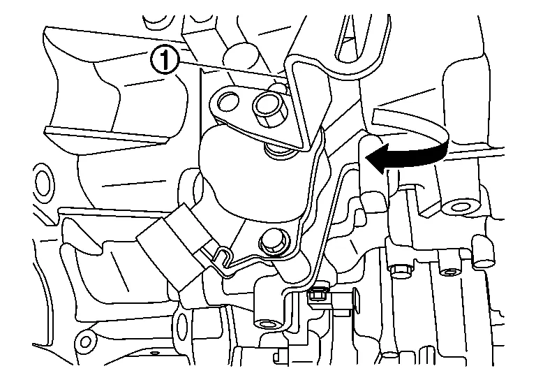
-
Rotate the lever clockwise to return the rod back to the P position.
-
If the lever does not rotate or if all detents are not detect, lift the sub-assembly and remove all sealant, and repeat from step 72.
Check the rotational smoothness of the primary pulley with the following procedure.
CAUTION:
Never insert fingers between the pulley and the transaxle case .
-
With clean hand, access the primary pulley from the bottom of the CVT to rotate.
-
Rotate the primary pulley by hand and confirm that the characteristic is the same as previously checked at step 47.
-
If the rotational characteristic worse than before the sub-assembly was replaced, perform the following.
-
Remove the side cover.
-
Remove the lubricating caps.
-
Wipe and clean the sealant completely from both the transaxle case rim and side cover rim.
-
Restart sub-assembly installation from Step 37.
-
Tighten pulley bracket bolts ( ) to the specified torque.
|
: Side cover |
Install the differential side oil seal using the universal driver handle [SST: ST35325000 (J-8092)] (A) and output seal installer (case side) [SST: KV31500800 (J–52283)] (B).
CAUTION:
Apply CVT fluid to the differential side of oil seal lip surface.
Set the CVT on the work bench with the side cover facing down on the bench.
Remove the converter housing which was temporarily installed with 3 bolts ( ).
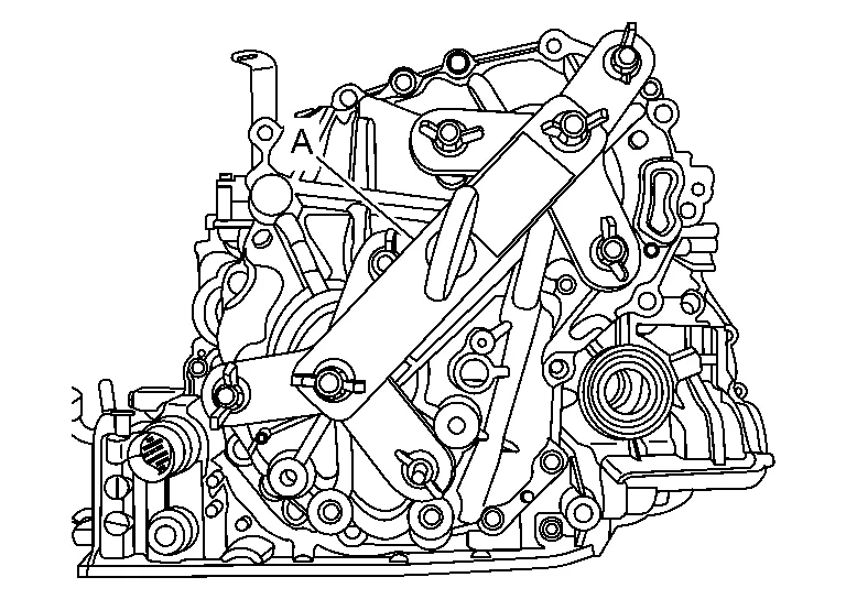
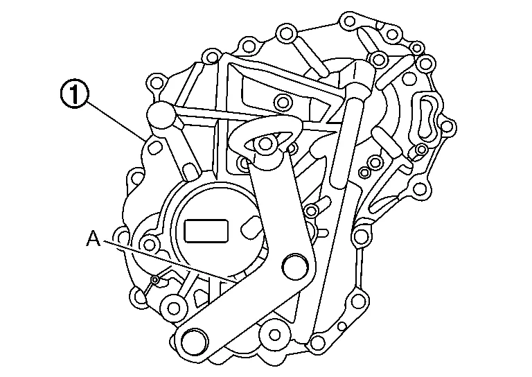
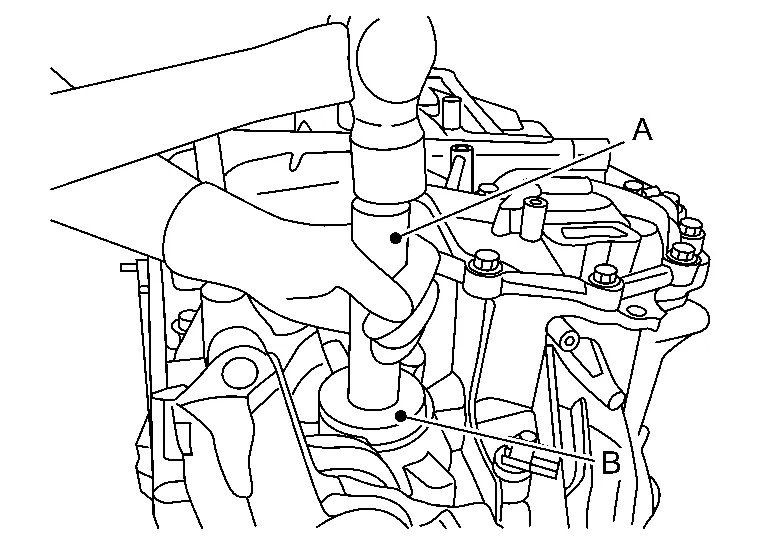
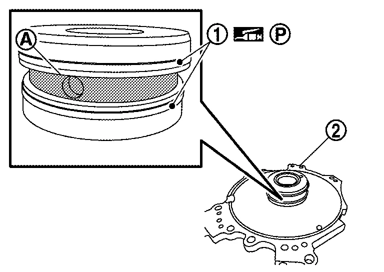
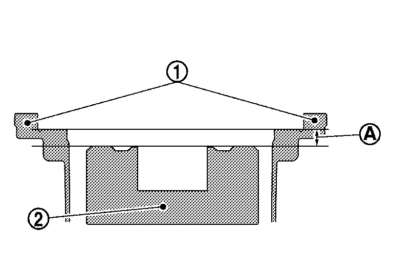
Calculate total end play with the following procedure.
CAUTION:
The total end play (A) must always be adjusted between the dummy cover and the forward clutch drum when a new sub-assembly is installed.
|
: Thrust bearing |
|
: Transaxle case |
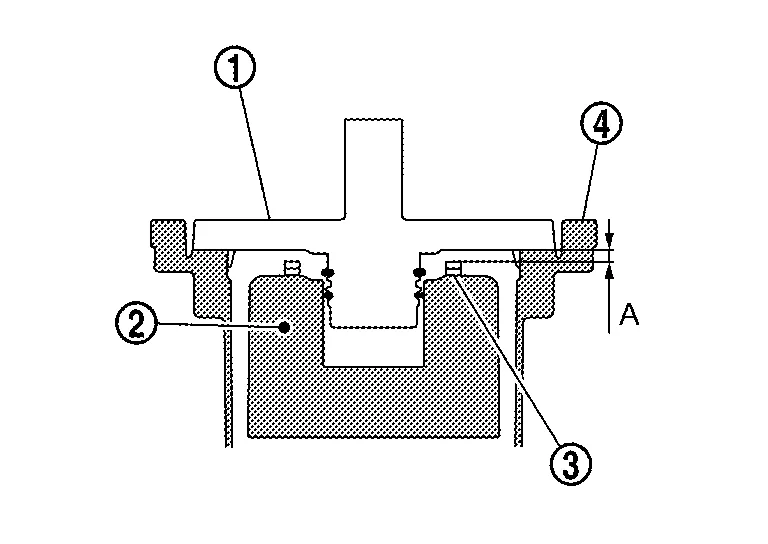
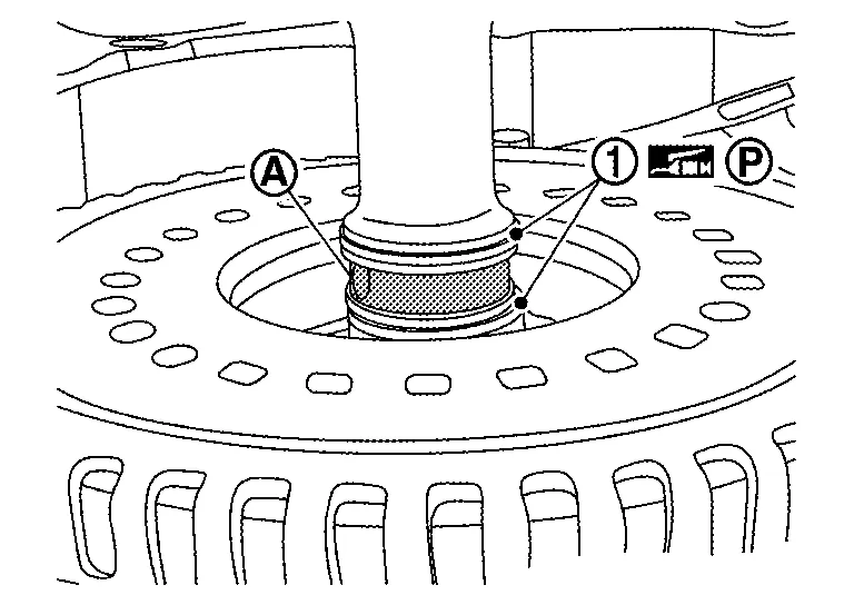
CAUTION:
-
The forward clutch is 1-3 mm (0.04 - 0.12 in) below the dummy cover surface.
-
If the gap is more than 1-3 mm (0.04 - 0.12 in), the component parts may be improperly installed. Refer to Trouble Shooting.
-
If the gap is less than 1-3 mm (0.04 - 0.12 in), the component parts may be missing or damaged.
-
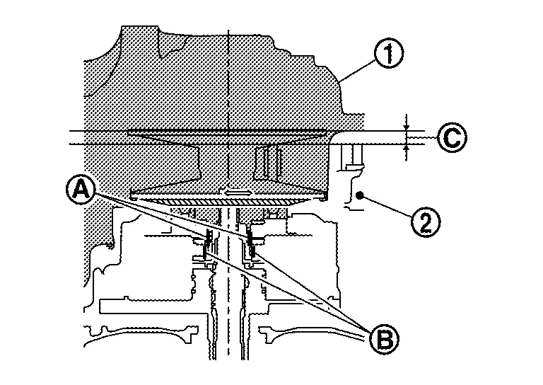
Measure the average distance (D) from the dummy cover installation surface of the transaxle case
to the needle bearing installation surface of the forward clutch drum .Average distance (D) : (D1 + D2)/2 A : Gauge block [SST: KV315J0400 (J-50271)] B : Digital Depth Gauge [SST: KV315J0500 (J-50272)] 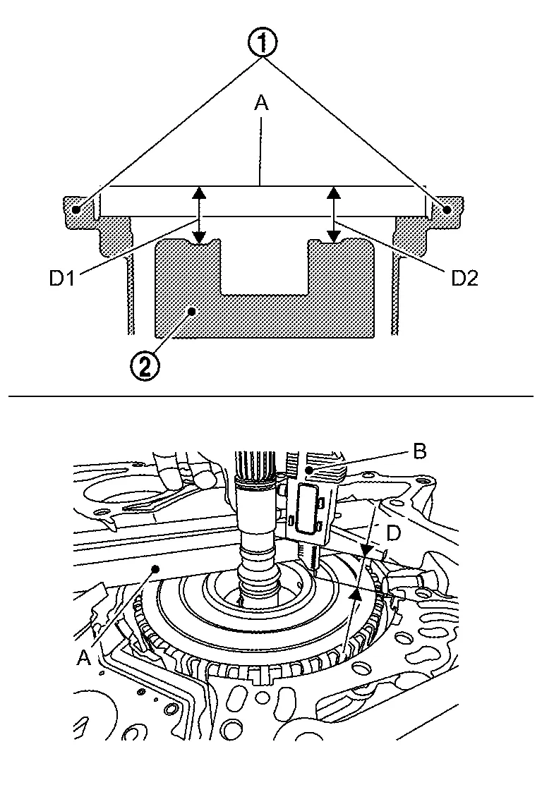
-
Clean the dummy cover surfaces
that contact the transaxle case and thrust beaning.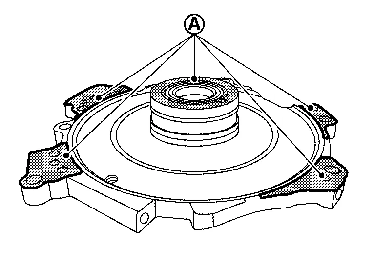
CAUTION:
-
Use parts cleaner or equivalent solvent and lint-free paper only.
-
Make sure the parts cleaner or solvents used are compatible with local requlations.
-
-
Measure the distance (H) from the edge of the dummy cover
to the installation surface on the transaxle case.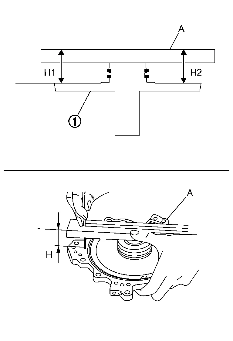
Average distance (H) : (H1 + H2)/2 A : Gauge block [SST: KV315J0400 (J-50271)] -
Measure the distance (J) from the edge of the dummy cover to the thrust race seats
.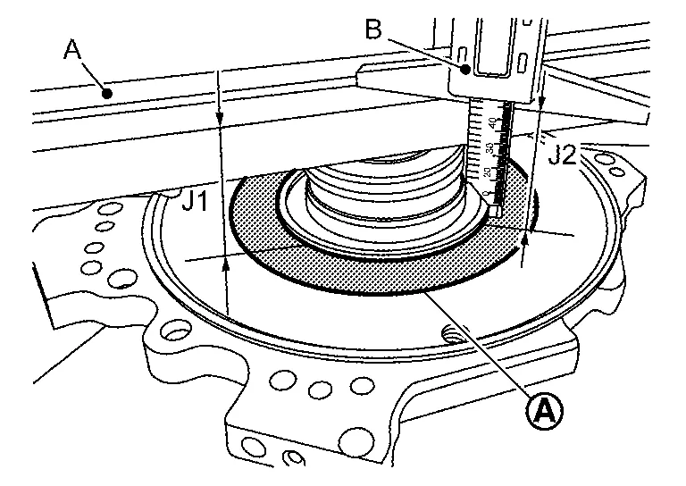
Average distance (J) : (J1 + J2)/2 A : Gauge block [SST: KV315J0400 (J-50271)] B : Digital Depth Gauge [SST: KV315J0500 (J-50272)] -
Measure thickness (E) of thrust bearing
without thrust race.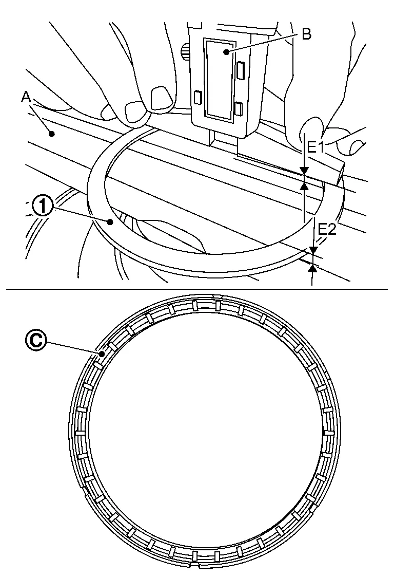
Average thickness (E) : (E1 + E2)/2 A : Gauge block [SST: KV315J0400 (J-50271)] B : Digital Depth Gauge [SST: KV315J0500 (J-50272)] : Roller side NOTE:
Roller side of thrust bearing must face down.
Calculate the total end play with the following formula, and choose the appropriate thrust race from table.
(D) - 20 mm + [(J) - (H)] - (E) = Total end play (A)
NOTE:
Never mesure from bearing race rip
.
Total end play (A) Bearing thickness (R) 0.90 - 1.08 mm 0.6 mm 1.09 - 1.29 mm 0.8 mm 1.30 - 1.50 mm 1.0 mm 1.51 - 1.70 mm 1.2 mm 1.71 - 1.90 mm 1.4 mm 1.91 - 2.10 mm 1.6 mm 2.11 - 2.30 mm 1.8 mm
Install the thrust bearing on the clutch drum.
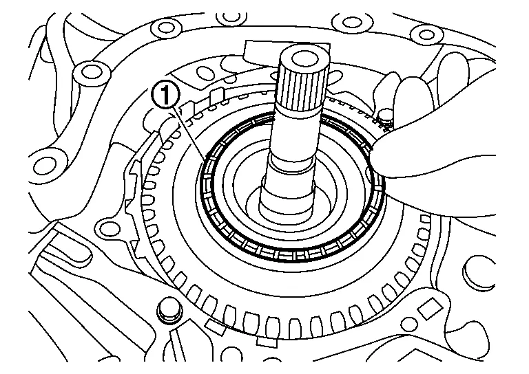
CAUTION:
-
The needle bearing side is the upper side.
-
The race side mates with the clutch drum surface.
Install the thrust race on the dummy cover .
CAUTION:
Apply petroleum jelly or equivalent to the thrust race to hold in place on the dummy cover.
Remove the baffle plate from the converter housing.
|
: Bolt |
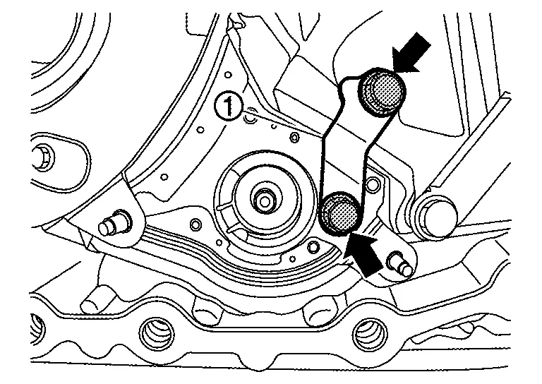
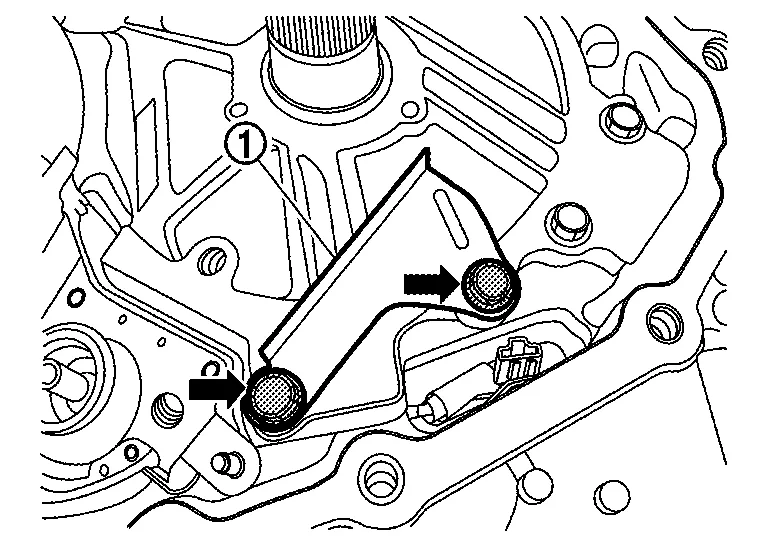
Remove the bolt ( ) and then remove the lubrication tube and bracket .
Clean hydraulic circuit of converter housing lubrication tube and dummy cover with parts cleaner and blowing air, check holes for blowing air.
CAUTION:
-
Never stand in front of the passages shown while using compressed air.
-
Wear eye / face protection when using compressed air and cleaning fluids.
-
Regulate air pressure up to a maximum of 517 kpa(5.27 kg/cm2, 75 psi).
Install the lubrication tube , bracket and bracket ().
Install the baffle plate to the converter housing.
|
: Bolt |
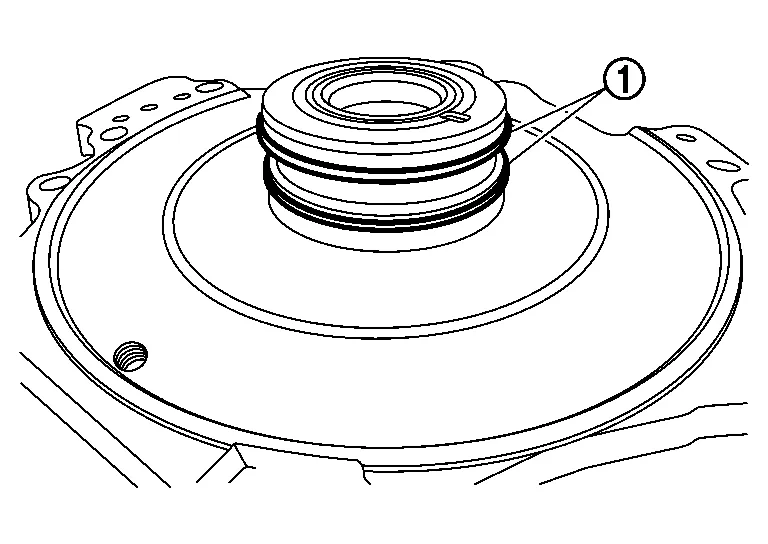
Apply petroleum jelly to the seal rings before installing the dummy cover to the transaxle case and clean the area .
CAUTION:
-
Seal rings are in their appropriate slots. Carefully reposition seals as necessary.
-
Seal rings must be in their correct positions during final assembly to prevent drivability issues.
Check the seal rings are in the correct positions and clean the area .
CAUTION:
-
Seal rings are in their appropriate slots. Carefully reposition seals as necessary.
-
Seal rings must be in their correct positions during final assembly to prevent drivability issues.
Install the dummy cover and chain guide .
CAUTION:
-
Never torque bolts (
) at this step. -
Check that the dummy cover is fully seated on the transaxle case. If dummy cover does not seated, forward clutch may be improperly installed. Refer to Trouble Shooting.
Install baffle plate and bracket with the related bolts finger tight. And tighten the bolts to the specified torque.
|
: 5.9 N·m (0.6 kg-m, 52 in-lb.) |
|
: 25.5 N·m (2.6 kg-m, 19 ft- lb). |
|
: 19.0 N·m (1.9 kg-m, 14 ft-lb.) |
Install the thrust washer onto the dummy cover .
NOTE:
Use petroleum jelly to hold the thrust washer in place.
Install the drive sprocket , driven sprocket , and chain as an assembly.
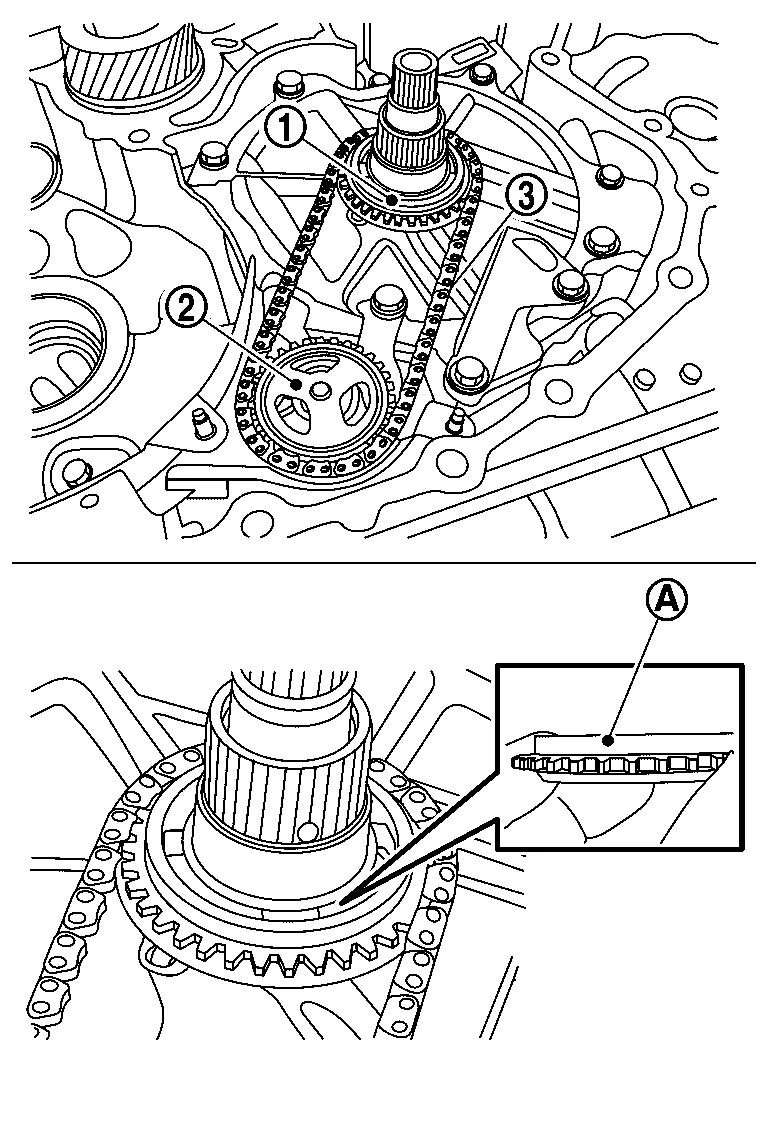
NOTE:
Wider edge on the drive sprocket is facing up.
Spread the snap ring using snap ring pliers.
Press down on the driven sprocket until it "snaps" and locks into place.
Pull up after install sprocket and check lockup to confirm adopt correctly.
Install the oil chain cover and tighten the mounting nut.
|
: Nut |
Install the differential assembly into the transaxle case.
CAUTION:
-
Clean differential assembly before installing.
-
Apply CVT fluid to the bearings and gear teeth before installing.
Install the reduction gear assembly into the transaxle case.
CAUTION:
-
Clean reduction gear assembly before installing.
-
Apply CVT fluid to the bearings and gear teeth before installing.
Install the new CVT fluid filter with grommet seal and O-ring .
CAUTION:
Apply CVT fluid to the grommet seal and O-ring.
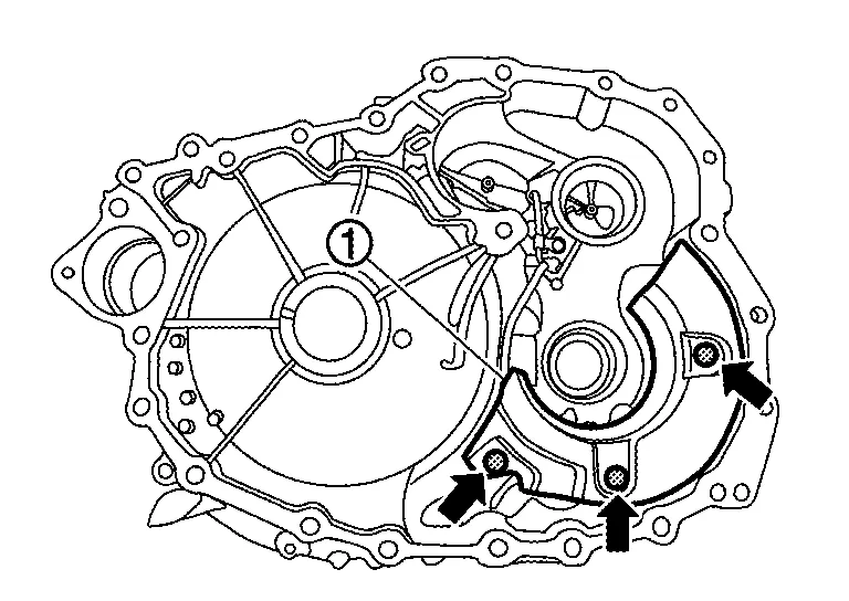
Install the CVT fluid filter cover and tighten the bolts ( ) to the specified torque.
Check that retaining pin of manual shaft locates on the original position.
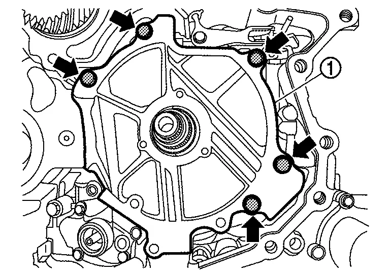
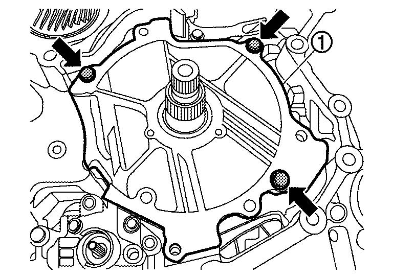
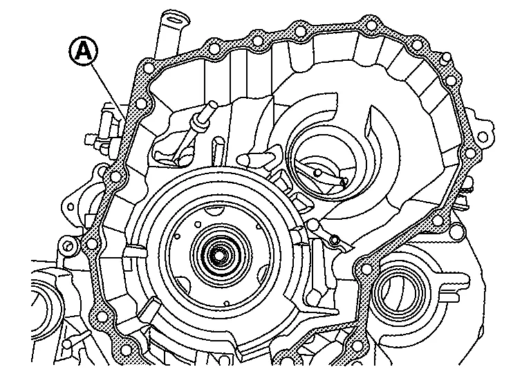
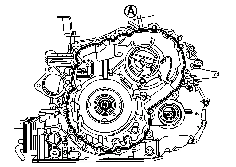
Apply Loctite 5460 on the converter housing installation surface of the transaxle case.
CAUTION:
-
Completely remove all moisture, oil and old sealant, etc. from the transaxle case and converter housing mounting surfaces.
-
The sealant width is 2.0 mm (0.08 in).
-
Check that the starting point and the ending point are about the middle between the bolts. The overlap both ends of the bead by 3 - 5 mm (0.12 - 0.20 in)
.
-
Be sure to apply, first sealant around the center bolt hole
, and next around the mating surfaces .
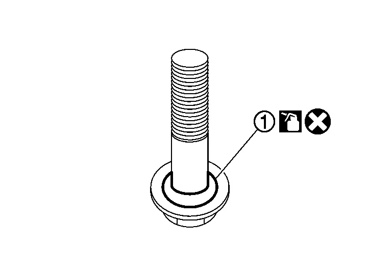
Install the converter housing onto the transaxle case and temporary tighten the new converter housing bolts. And then, tighten the bolts to specified torque in the order shown.
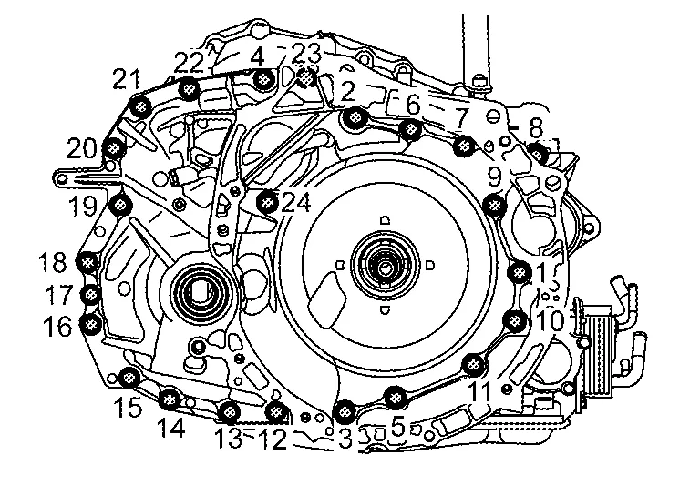
CAUTION:
Never reuse the converter housing bolts.
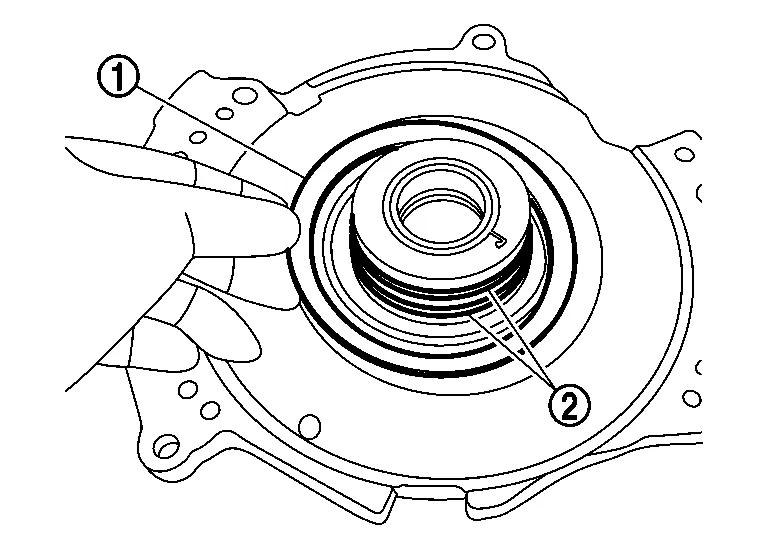
Install the new converter housing oil seal evenly using the oil pump seal installer [SST: KV31500700 (J-50818)] (A)
| (B) | : 0.5 mm (0.02 inch) |
NOTE:
-
Set the torque converter housing flat during installation.
-
Apply CVT fluid to the seal lip surface.
-
Converter housing oil seal pulling direction is used as the reference.
FWD
Install the differential side oil seal using the output seal installer (troque converter side) [SST: KV31500900 (J-52284)] (A) and universal driver handle [SST: ST35325000 (J-8092)] (B).
|
: Converter housing |
CAUTION:
Apply CVT fluid to the differential side oil seal lip surface.
Install the O-ring on the input shaft.
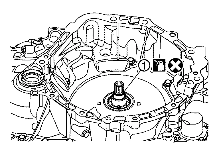
CAUTION:
-
Never reuse the O-ring.
-
Apply the CVT fluid when installing the O-ring.
Install the lip seal to the transaxle case.
CAUTION:
-
Never reuse lip seal.
-
Apply petroleum jelly to lip seal.
| : Front |
Install the control valve to the transaxle case.
CAUTION:
-
Never drop the control valve, ratio control valve and manual shaft.
-
Ensure the harness
is correctly routed and does not get pinched.
Secure the control valve using bolts , and .
CAUTION:
Ensure the harness is correctly routed and does not get pinched.
NOTE:
-
Leave bolt holes
blank at this step. -
Install bolts
without the strainer bracket.
| Bolt | Bolt length mm (in) | Number of bolts |
|---|---|---|
|
54 (2.13) | 7 |
|
44 (1.73) | 2 |
|
25 (0.98) | 2 |
| : Front |
Connect the control valve harness connector .
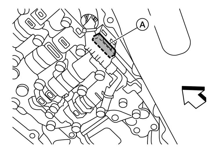
| : Front |
CAUTION:
Securely insert the harness connector until it clicks and locks.
Install the CVT fluid temperature sensor bracket to the valve body with bolt .
| Bolt | Bolt length mm (in) | Number of bolts |
|---|---|---|
|
54 (2.13) | 1 |
NOTE:
Leave bolt hole blank as it will be used to secure the oil strainer at a later step.
Install new O-ring to oil strainer assembly.
CAUTION:
-
Never reuse O-ring.
-
Apply CVT fluid to O-ring.
NOTE:
New oil strainers come with a new O-ring already installed.
Install new oil strainer with bolts .
| Bolt | Bolt length mm (in) | Number of bolts |
|---|---|---|
|
54 (2.13) | 2 |
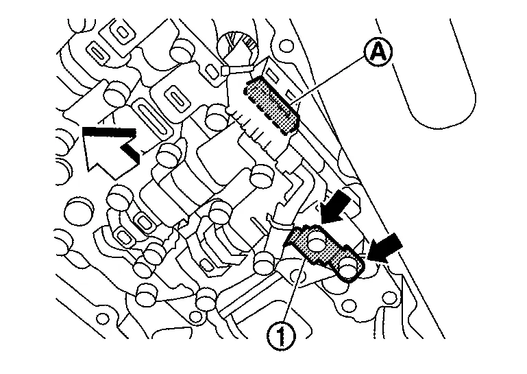
Install the manual plate while aligning the ends as shown.
-
Align the slot of the manual plate with the manual shaft
. -
Align the end of the manual plate with the cutout of the manual valve.
CAUTION:
Install the end of the manual plate into the cutout of the manual valve.
|
: Cutout |
| : Front |
Install the spring washer and the lock-nut , and then tighten to the specified torque.
CAUTION:
To tighten nut, fix manual plate with suitable tool.
Install the magnets in the oil pan in their original location.
CAUTION:
Completely clean the iron powder from the magnet area of oil pan and the magnet.
Install the oil pan to the transaxle case with the following procedure.Install the oil pan gasket to the oil pan.
CAUTION:
-
Completely wipe out any moisture, oil, and old gasket from the oil pan gasket surface and bolt hole of oil pan and transaxle case.
-
Never reuse oil pan gasket.
| : Front |
Install drain plug gasket to drain plug.
CAUTION:
Never reuse drain plug gasket.
Install drain plug to oil pan.
Install new QR code sticker on Transmission Range (inhibitor) switch .
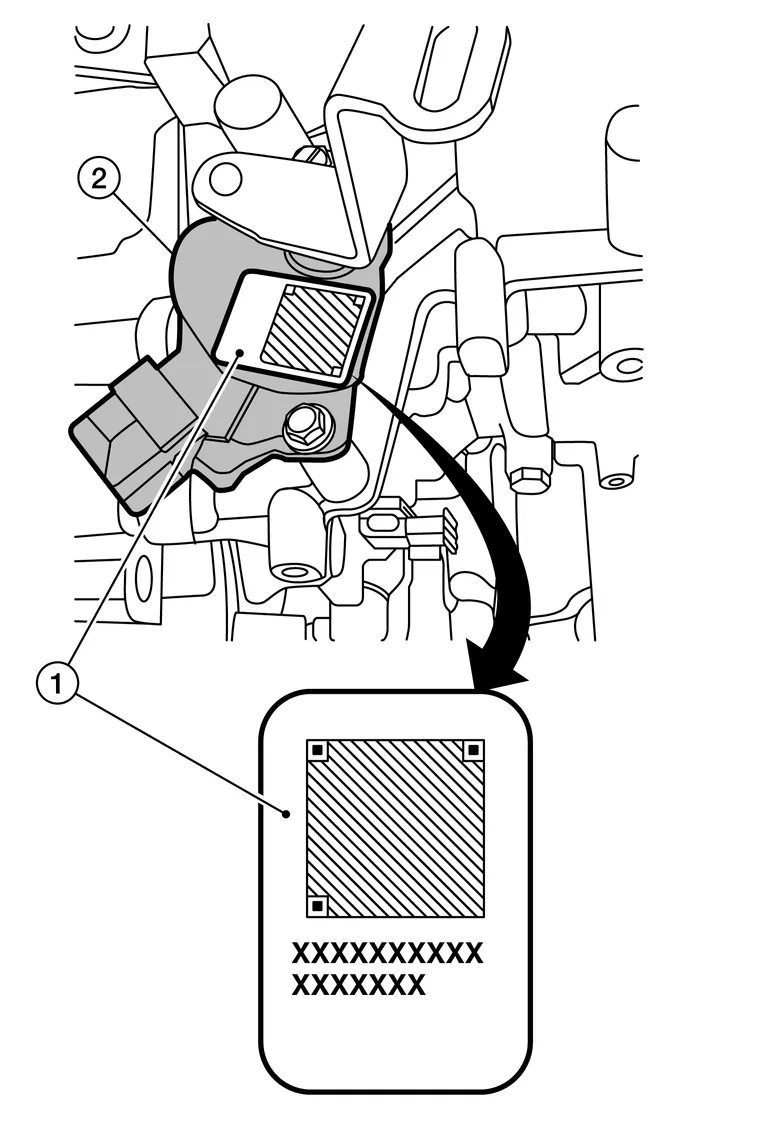
NOTE:
If sticker is not included with parts, contact Powertrain Call Center to report.
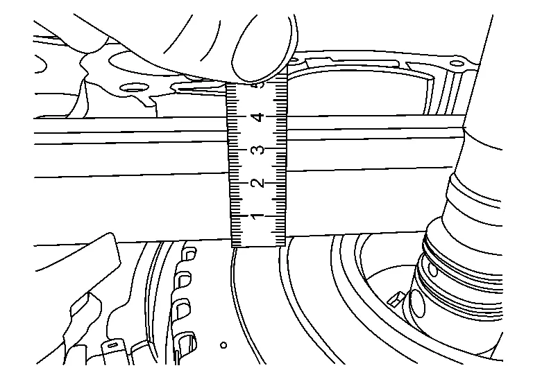
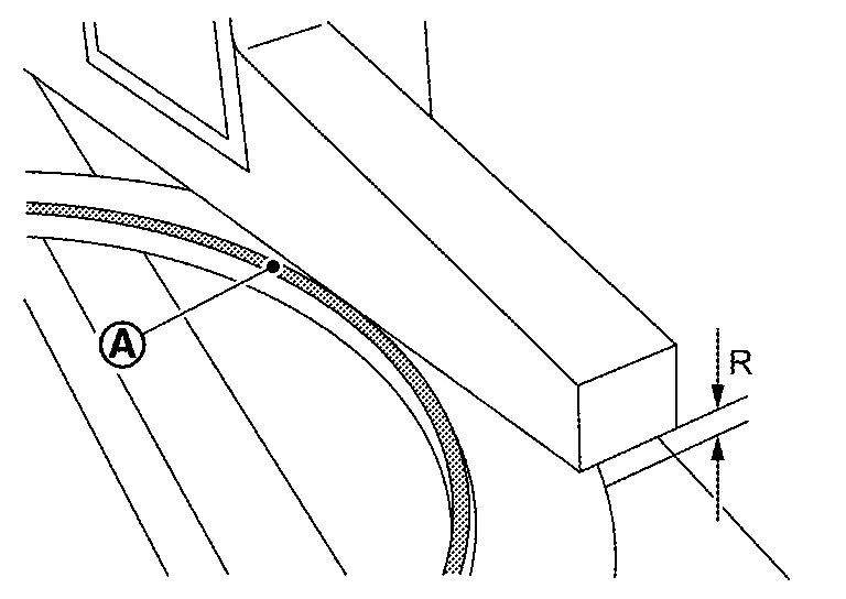
Install the torque converter to the transaxle in the following procedure.
CAUTION:
Insert the pawl of the torque converter to the drive sprocket hole on the transaxle assembly side.
After inserting a torque converter to the CVT, check dimension (A) with in the reference value limit.
| (B) | : Scale |
| (C) | : Straightedge |
Install the primary speed sensor.
CAUTION:
-
Never reuse O-ring.
-
Apply CVT fluid to the O-ring.
Install the transaxle assembly into the Nissan Murano vehicle. Refer to Removal and Installation - FWD (FWD) or Removal and Installation - AWD (AWD).
If replacing CVT, flush the CVT fluid cooler and lines. Refer to CVT Fluid Cooler Flush.
Fill the transaxle assembly with CVT fluid. Refer to Refilling.
Perform "ADDITIONAL SERVICE WHEN REPLACING CONTROL VALVE." Refer to Description.
The Dummy Cover Will Not Sit Flush
NOTE:
-
If the dummy cover does not sit flush, the forward clutch assembly may not be fully seated. The forward clutch assembly is not fully seated if it is not below the surface that the dummy cover bolts to.
: Transaxle case : Forward clutch assembly : The clearance between the dummy cover and the forward clutch assembly -
Always handle the forward clutch assembly by the input shaft.
-
Remove the dummy cover
.
-
Pull up the forward clutch assembly
by the input shaft to remove the entire forward clutch assembly.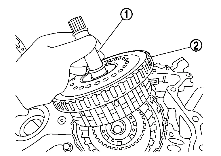
-
Using an appropriate tool (A) , Gently align the layers of the forward clutch assembly
.
: Forward clutch assembly -
Re-insert the entire forward clutch assembly
while holding the input shaft .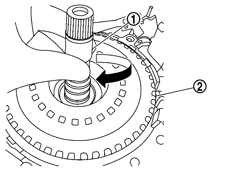 NOTE:
NOTE:
-
Gently jiggle the input shaft until the forward clutch assembly seats below case lip.
-
If the forward clutch assembly
does not seat, rotate back and forth from the input shaft and jiggle. -
If the clutch pack still does not seat, repeat from step 3
-

 Torque Converter and Converter Housing Oil Seal
Exploded View
Transaxle assembly
Converter housing oil seal
Torque converter
: Always replace after every disassembly.
: Apply CVT Fluid
Disassembly
Remove transaxle assembly...
Other information:
Nissan Murano (Z52) 2015-2024 Service Manual: Wiper
CONSULT Function (BCM - WIPER) ECU IDENTIFICATIONThe BCM part number is displayed.SELF DIAGNOSTIC RESULTRefer to DTC Index.DATA MONITOR Monitor Item [Unit] Description PUSH SW [On/Off] Indicates condition of push-button ignition switch. VEH SPEED 1 [km/h] Indicates Nissan Murano vehicle speed signal received from ABS on CAN communication line...
Nissan Murano (Z52) 2015-2024 Owners Manual: Switch operation
WARNING In freezing temperatures the washer solution may freeze on the windshield and obscure your vision whichmaylead to an accident. Warm the windshield with the defroster before you wash the windshield. CAUTION Do not operate the washer continuously for more than 30 seconds...
Categories
- Manuals Home
- Nissan Murano Owners Manual
- Nissan Murano Service Manual
- Vehicle Dynamic Control (VDC) OFF switch
- How to enable/disable the LDW system
- Tire rotation
- New on site
- Most important about car
Seatback pockets

Theremaybe one or two seatback pockets located on the back of the driver and passenger seats. The pockets can be used to store maps.
WARNING