Nissan Murano: Steering / Steering Control System :: Ecu Diagnosis Information. Power Steering Control Module
 NOTE:
NOTE:
The following table includes information (items) inapplicable to this Nissan Murano vehicle: For information (items) applicable to this vehicle, refer to CONSULT display items.
| Monitor item | Data monitor | ||
|---|---|---|---|
| Condition | Display value | ||
| BATTERY VOLT | Engine running | Battery voltage (V) | |
| STEERING ANGLE | The steering wheel is not steered. | Approx. 0.0 deg | |
| The steering wheel is steered. | Displays steering angle (deg) | ||
| STR ANG SPD | The steering wheel is not steered. | Approx. 0.0 deg/s | |
| The steering wheel is steered. | Displays steering angle speed (deg/s) | ||
| MOTOR CURRENT | Engine running | Steering wheel: Not steering (There is no steering force.) | MAX approx. 10 A*1 |
| Steering wheel: Right or left turn | Displays consumption current of power steering control module (A) | ||
| MTR REV SPD COMM | Engine running | Steering wheel: Not steering (There is no steering force.) | Shows an almost constant value (rpm) |
| Steering wheel: Right or left turn | The value changes as a steering speed (rpm) | ||
| MTR REV SPD | Engine running | Steering wheel: Not steering (There is no steering force.) | Shows an almost constant value (rpm)*2 |
| Steering wheel: Right or left turn | The value changes as a steering speed (rpm)*2 | ||
| C/U TEMP | Engine running | Displays temperature of inside power steering control module (°F or °C) | |
| C/U TEMP A | Engine running | Displays temperature of inside power steering control module (°F or °C) | |
| MTR ASSIST | Engine running | 100%*3 | |
| ESTM VHCL SPD | Nissan Murano Vehicle stopped | 0.00 mph or km/h | |
| While driving |
Approximately equal to the indication on speedometer*4 (inside of ±10%) |
||
| WARNING LAMP | Hydraulic pump electric power steering warning lamp: ON | On | |
| Hydraulic pump electric power steering warning lamp: OFF | Off | ||
| ENGINE STATUS | Engine not running | STOP | |
| Engine running | RUN | ||
| Engine cranking | CRANK | ||
| VHCL SPD JUDGE | Nissan Murano Vehicle speed signal can be received via CAN communication. | OK | |
| Vehicle speed signal cannot be received via CAN communication. | NG | ||
*1: The value changes according to load of power steering motor.
*2: This is in close agreement with a motor speed command value. Although a quick steering operation may cause disagreement, this is not a malfunction.
*3: Usually, 100% is displayed. An excessive steering operation gradually lowers the percentage. When left standing, the percentage returns to 100%.
*4: This may not agree with the speedometer indication immediately after ignition switch ON. This is not a malfunction.
TERMINAL LAYOUT
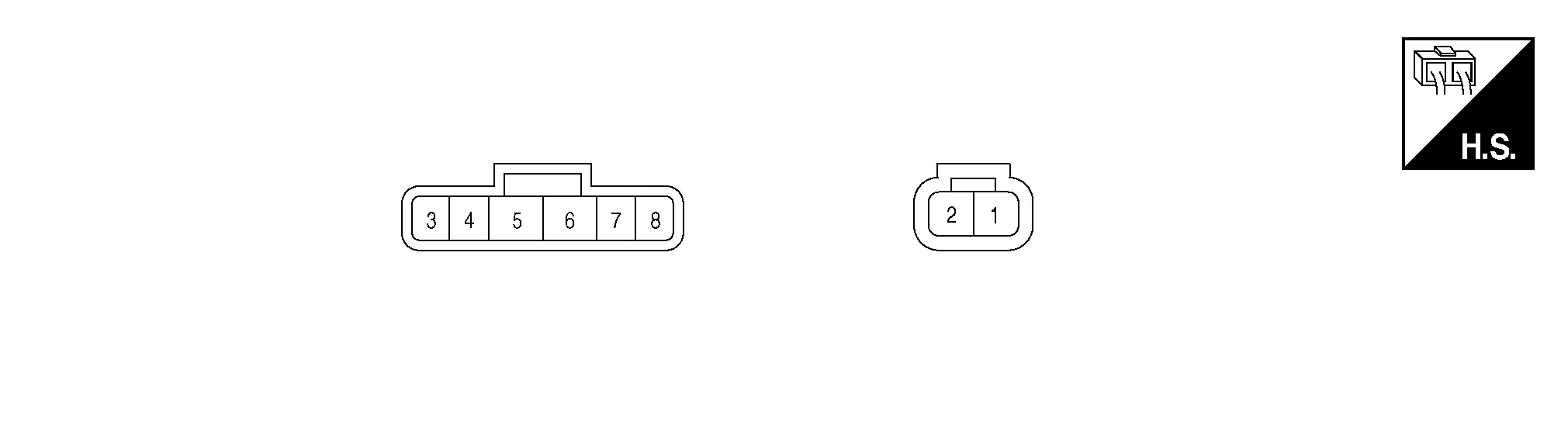
PHYSICAL VALUES
|
Terminal No. (Wire Color) | Description | Condition |
Value (Approx.) | |||
|---|---|---|---|---|---|---|
| + | − | Signal name | Input/Output | |||
|
1 (W) |
Ground | Battery power supply | Input | Always | Battery voltage | |
|
2 (B) |
Ground | Ground | — | Always | 0 V | |
|
5 (BR) |
Ground | Ignition power supply | Input | Ignition switch: ON | Battery voltage | |
| Ignition switch: OFF | 0 V | |||||
|
7 (P) |
— | CAN-Low | Input/Output | — | — | |
|
8 (L) |
— | CAN-High | Input/Output | — | — | |
When an error occurs in the hydraulic pump electric power steering system, fail-safe brings the system to a halt (manual steering) or restricted (constant steering assist level) state. When the system is in a halt state, fail-safe turns ON the hydraulic pump electric power steering warning lamp to warn the driver that the hydraulic pump electric power steering system is in the manual steering state.
| DTC | Fail-safe condition |
|---|---|
| C1143 | Certain steering assist force |
| C1601 | Manual steering state |
| C1602 | Manual steering state |
| C1606 | Manual steering state |
| C1607 | Certain steering assist force |
| C1608 | Manual steering state |
| C1609 | Certain steering assist force |
| U1000 |
Normal control
If the cause is in a different ECU, the state changes to fixed steering assist force. |
-
When the steering wheel is operated repeatedly or turned all the way for a long period during parking or low-speed driving, the function of the hydraulic pump electric power steering system becomes limited to prevent the system from overheating. If the steering wheel is operated furthermore, the hydraulic pump electric power steering system stops and the hydraulic pump electric power steering system warning lamp may be turned ON. In this case, the steering wheel operation temporarily becomes hard. This is not a malfunction. When the engine is turned OFF (ignition switch OFF) and steering operation is stopped for a while, the temperature of the hydraulic pump electric power steering system decreases and the steering operation returns to normal after restarting the engine.
-
Then, the hydraulic pump electric power steering system warning lamp turns OFF. If the system is OFF under the protection state, the hydraulic pump electric power steering system warning lamp turns ON to warn that the system is in the manual steering state. (This is not a system malfunction.) In addition, the following DTC remains to distinguish from a malfunction:
| DTC | Nissan Murano Vehicle condition |
|---|---|
| C160A | The system temporarily enters the manual steering state. (This is not a hydraulic pump electric power steering system malfunction.) |
When multiple DTCs are detected simultaneously, check one by one depending on the following priority list:
| Priority | Priority order item (DTC) |
|---|---|
| 1 |
|
| 2 |
|
| 3 |
|
| 4 |
|
| 5 |
|
| DTC | Items (CONSULT screen terms) | Reference |
|---|---|---|
| C1143 | ST ANG SEN CIRCUIT | DTC Description |
| C1601 | BATTERY VOLT | DTC Description |
| C1602 | NO TUNING SET | DTC Description |
| C1606 | EPS MOTOR | DTC Description |
| C1607 | EEPROM | DTC Description |
| C1608 | CONTROL UNIT | DTC Description |
| C1609 | CAN VHCL SPEED | DTC Description |
| C160A | HEAT PROTECTION | DTC Description |
| U1000 | CAN COMM CIRCUIT | DTC Description |
NOTE:
If two or more DTCs are detected, refer to DTC Inspection Priority Chart.
 Diagnosis System (power Steering Control Module)
CONSULT Function
CAUTION:
After disconnecting the CONSULT vehicle interface (VI) from the data link connector, the ignition must be cycled OFF → ON (for at least 5 seconds) → OFF...
 Steering Control System :: Basic Inspection. Diagnosis and Repair Work Flow
Work Flow
DETAILED FLOWINTERVIEW THE CUSTOMER
Clarify customer complaints before inspection. First of all, perform an interview utilizing Diagnostic Work Sheet and reproduce symptoms to understand them fully...
Other information:
Nissan Murano (Z52) 2015-2024 Owners Manual: Maximum trailer loads
Never allow the total trailer load to exceed the value specified in the “Towing Load/Specification” chart found in this section. The total trailer load equals trailer weight plus its cargo weight. The maximum Gross Combined Weight Rating (GCWR) should not exceed the value specified in the following Towing Load/Specification Chart...
Nissan Murano (Z52) 2015-2024 Service Manual: C1761 Temperature Data Fl
DTC Description NOTE: The Signal Tech II Tool [– (J-50190)] can be used to perform the following functions: Refer to the Signal Tech II User Guide for additional information. Activate and display TPMS sensor IDs Display tire pressure reported by the TPMS sensor Read TPMS DTCs Register TPMS sensor IDs DTC DETECTION LOGIC DTC No...
Categories
- Manuals Home
- Nissan Murano Owners Manual
- Nissan Murano Service Manual
- High Beam Assist (if so equipped)
- Shift lock release
- Passenger compartment
- New on site
- Most important about car
Luggage hooks

When securing items using luggage hooks located on the back of the seat or side finisher do not apply a load over more than 6.5 lbs. (29 N) to a single hook.
The luggage hooks that are located on the floor should have loads less than 110 lbs. (490 N) to a single hook.