Nissan Murano: Instrument Panel :: Removal and Installation / Glove Box Assembly and Housing
REMOVAL
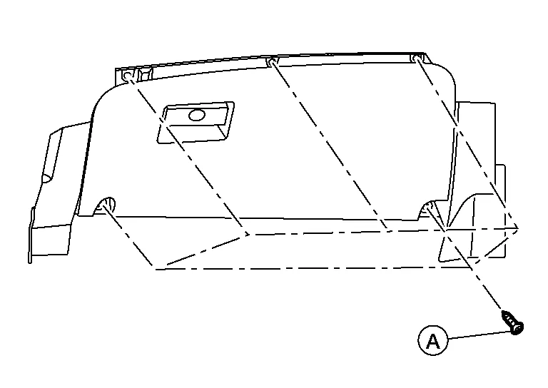
Remove glove box assembly screws (A).
 NOTE:
NOTE:
Open glove box lid to access upper screws.
Using a suitable tool, release clips.
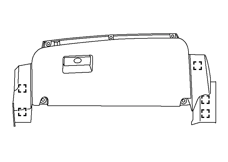
 : Metal clip
Disconnect harness connectors from glove box assembly.
Remove glove box assembly.
INSTALLATION
Installation is in the reverse order of removal.
 Instrument Lower Panel Lh
Removal and Installation
WARNING:
Before servicing the SRS, turn ignition switch OFF, disconnect both battery terminals then wait at least three minutes...

Other information:
Nissan Murano (Z52) 2015-2024 Owners Manual: Engine cooling system
The engine cooling system is filled at the factory with a pre-diluted mixture of 50% Genuine NISSAN Long Life Antifreeze/Coolant (blue) and 50% water to provide year-round antifreeze and coolant protection. The antifreeze solution contains rust and corrosion inhibitors...
Nissan Murano (Z52) 2015-2024 Service Manual: Seat Belt Indctr Lamp Is On, Pass Air Bag Indctr Is on or Off
Diagnosis Procedure Vehicle conditions: Seat belt indicator lamp is ON, passenger air bag indicator lamp is ON or OFF. Passenger seat is unoccupied. Driver seat belt is buckled. Front seat belt buckle switch RH harness and front seat belt buckle switch RH are OK (buckle passenger seat belt to check if seat belt indicator lamp turns OFF, driver seat belt needs to be buckled)...
Categories
- Manuals Home
- Nissan Murano Owners Manual
- Nissan Murano Service Manual
- How to enable/disable the LDW system
- Jacking up vehicle and removing the damaged tire
- All-Wheel Drive (AWD) (if so equipped)
- New on site
- Most important about car
Driver and passenger supplemental knee air bag

Driver’s side
The knee air bag is located in the knee bolster, on the driver’s and passenger’s side. All of the information, cautions and warnings in this manual apply and must be followed. The knee air bag is designed to inflate in higher severity frontal collisions, although it may inflate if the forces in another type of collision are similar to those of a higher severity frontal impact. It may not inflate in certain collisions.

Passenger’s side