Nissan Murano: Engine / Engine Mechanical :: Unit Disassembly and Assembly. Cylinder Block
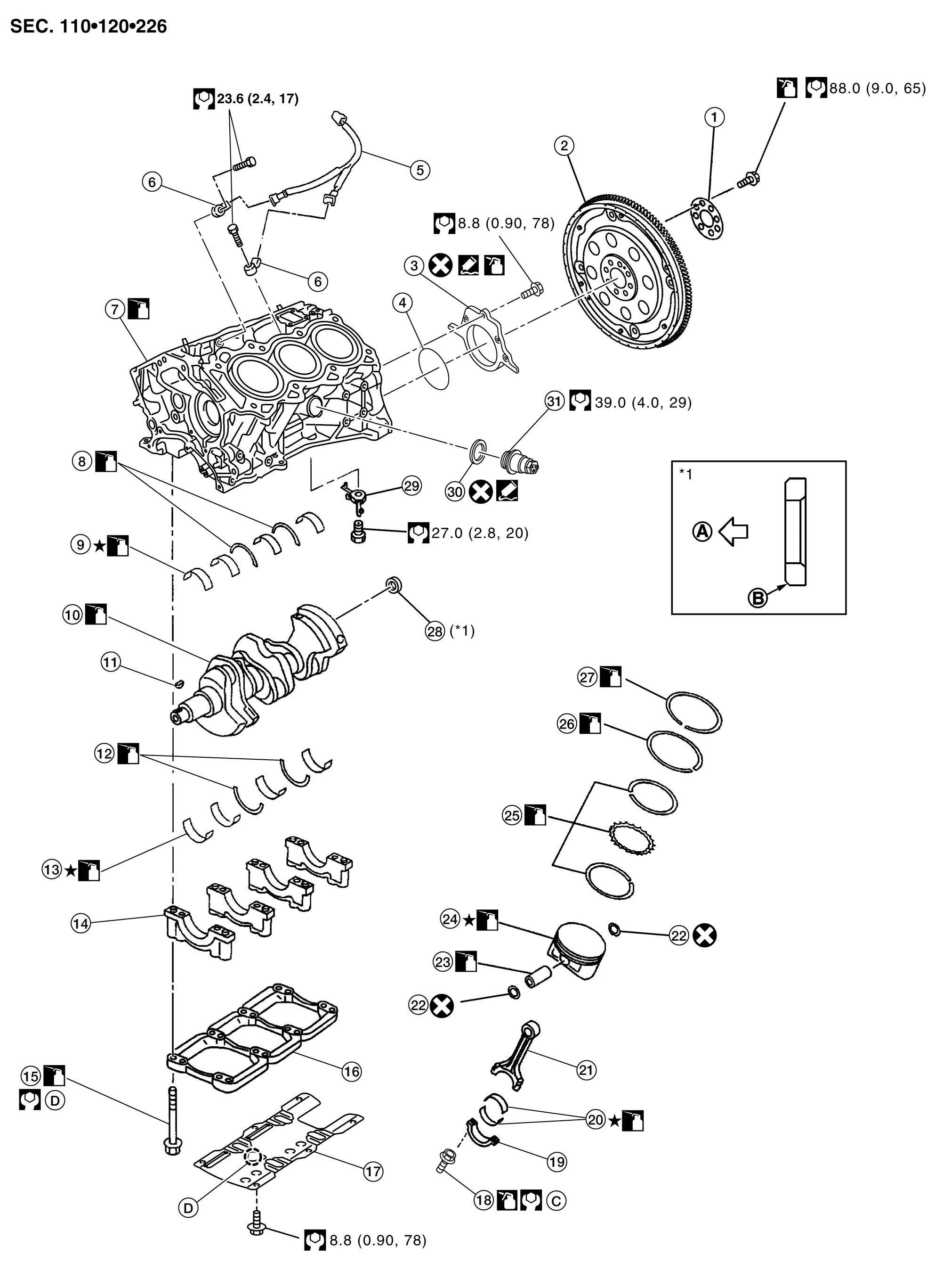
| 1. | Reinforcement plate | 2. | Drive plate | 3. | Rear oil seal retainer |
| 4. | Rear oil seal | 5. | Sub harness | 6. | Knock sensor |
| 7. | Cylinder block | 8. | Thrust bearing (upper) | 9. | Main bearing (upper) |
| 10. | Crankshaft | 11. | Crankshaft key | 12. | Thrust bearing (lower) |
| 13. | Main bearing (lower) | 14. | Main bearing cap | 15. | Main bearing cap bolt |
| 16. | Main bearing beam | 17. | Baffle plate | 18. | Connecting rod bolt |
| 19. | Connecting rod bearing cap | 20. | Connecting rod bearing | 21. | Connecting rod |
| 22. | Snap ring | 23. | Piston pin | 24. | Piston |
| 25. | Oil ring | 26. | Second ring | 27. | Top ring |
| 28. | Pilot converter | 29. | Oil jet | 30. | Gasket |
| 31. | Cylinder block heater (if equipped) | A. | Crankshaft side | B. | Chamfered |
| C. | Refer to Disassembly and Assembly. | D. | Front mark |
CAUTION:
-
Apply new engine oil to parts as marked in illustrations before installation.
-
Place removed parts such as bearings and bearing caps in their proper order and direction.
-
When installing the connecting rod nuts and main bearing cap bolts, apply new engine oil to the threads and mating surfaces
-
Do not allow any magnetic materials to contact the signal plate teeth on the drive plate.
DISASSEMBLY
Remove the engine assembly. Refer to Removal and Installation (FWD) or Removal and Installation (AWD).
Remove the drive plate. Refer to Exploded View.
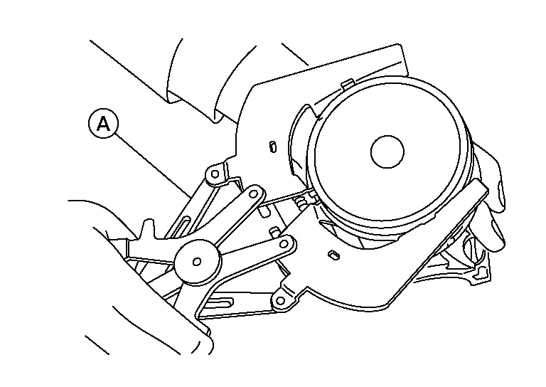
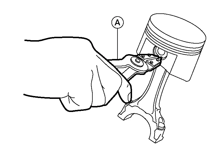
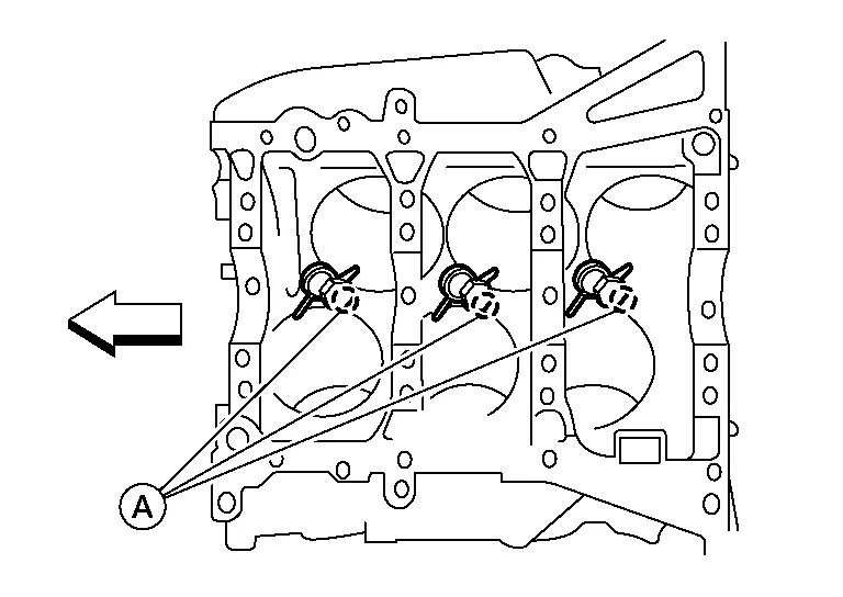
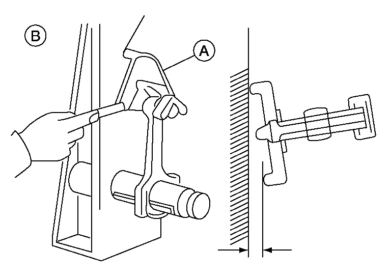
Remove pilot converter using suitable tool (A).

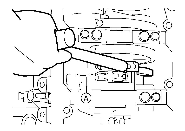
Cut away liquid gasket and remove rear oil seal retainer using suitable tool (A). Refer to Precaution for Liquid Gasket.

| Tool number (A) | : KV10111100 (J-37228) |
CAUTION:
-
Be careful not to damage mounting surface.
-
If rear oil seal retainer is removed, replace it with a new one.
 NOTE:
NOTE:
Rear oil seal and retainer form a single part and are replaced as an assembly.
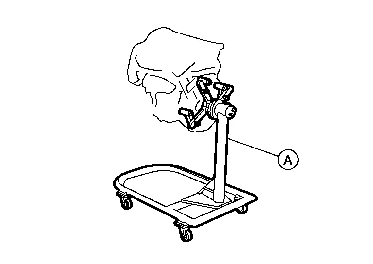
Install the engine on engine stand (A). Any commercially available engine stand (A) can be used.
CAUTION:
-
Use an engine stand (A) that has a load capacity [approximately 240kg (529 lb) or more] large enough for supporting the engine weight.
-
Before removing the hanging chains, make sure the engine stand (A) is stable and there is no risk of overturning.
Remove the knock sensor.
CAUTION:
Carefully handle sensor to avoid shocking it.
Drain engine coolant. Refer to Changing Engine Coolant.
Drain engine oil. Refer to Changing Engine Oil.
Remove the upper oil pan. Refer to Removal and Installation (Upper Oil Pan).
Remove the crankshaft pulley.
-
Use a suitable tool to prevent the crankshaft from turning.
Remove the timing chain. Refer to Removal and Installation.
Remove the cylinder head. Refer to Removal and Installation.
Remove the piston and connecting rod assemblies.
-
Before removing the piston and connecting rod assembly, check the connecting rod side clearance. Refer to Connecting Rod Bearing.
Remove the connecting rod bearings.
CAUTION:
When removing the connecting rod side bearings, note the installation position. Keep them in the correct order.
Remove the piston rings from the piston.
-
Use a piston ring expander (A).
CAUTION:
-
When removing the piston rings, be careful not to damage the piston. Do not expand the rings excessively.
-
Be careful to mark the rings if they are to be reused so they are installed in their original position.
-
Before removing the piston rings, check the piston ring side clearance. Refer to Inspection.
Remove the piston from the connecting rod as follows.
CAUTION:
Do not reuse snap rings, always replace with new ones.
Heat the pistons to 60° - 70°C (140° - 158°F) utilizing suitable tool (A).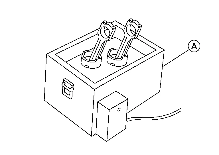
WARNING:
Pistons contain heat. When working, wear protective equipment to avoid getting burned.
Push out the piston pin with a suitable tool with an outer diameter of approximately 20 mm (0.8 in).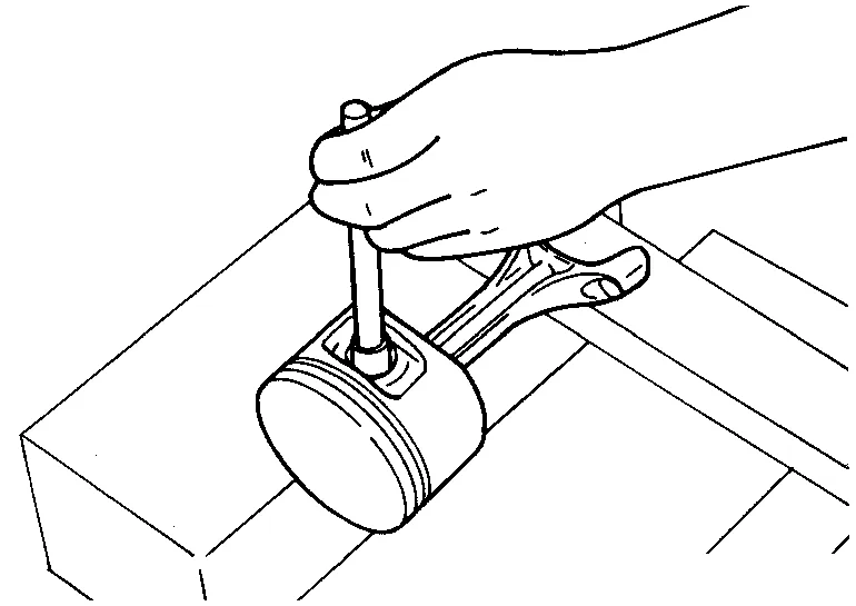
Remove the baffle plate from the main bearing beam.
Loosen the bolts in the reverse order shown and remove the main bearing beam, bearing caps and crankshaft.
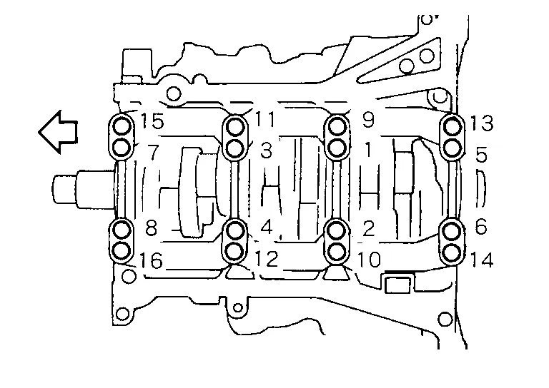
-
Before loosening the main bearing cap bolts, measure the crankshaft side clearance.
Refer to Inspection.

: Engine front
Remove the oil jets (A) and dowel pins.
Remove the main bearings and thrust bearings from the cylinder block and main bearing caps.
-
When removing them, note the direction and position. Keep them in the correct order for installation.
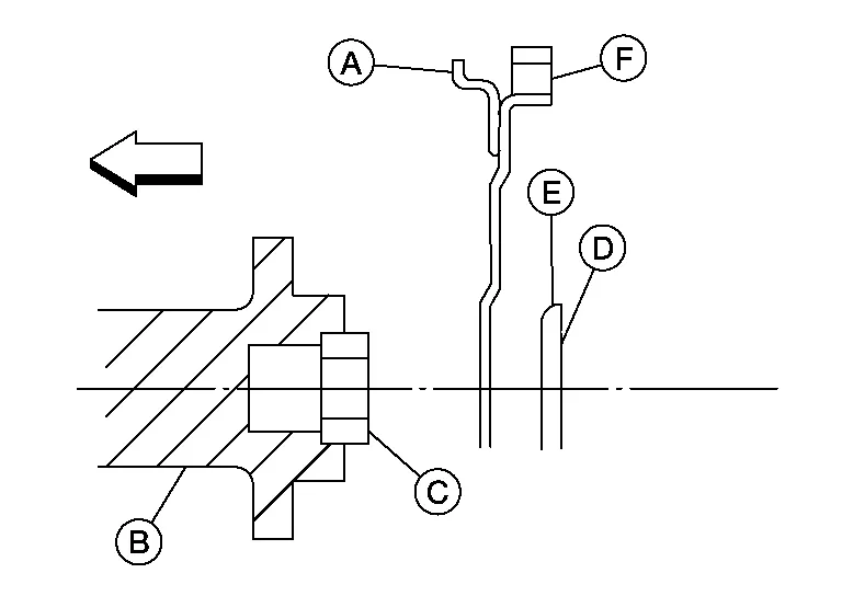
Remove the water drain plug (A) and (D), connector bolt (E) from the cylinder block.
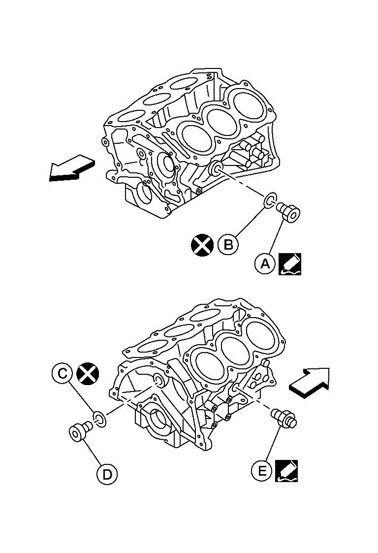
CAUTION:
-
Do not reuse copper sealing washers (B) and (C).
-
Do not reuse metal washer (if equipped).
NOTE:
-
Drain plug (D) can be equipped with a copper sealing washer or metal washer.
-
(A) may not be plug but block heater (if equipped).
| : Engine front |
ASSEMBLY
Blow out the coolant and oil passages and cylinder bore to remove any foreign materials.
CAUTION:
Use goggles to protect your eyes.
Install the cylinder block drain plugs.
NOTE:
Drain plug (D) can be equipped with a copper sealing washer or metal washer.
-
Install the water drain plug (A) and (D), connector bolt (E) into the cylinder block and tighten to specification.
CAUTION:
-
Use Genuine RTV silicone sealant or equivalent. Refer to Recommended Chemical Products and Sealants.
-
Do not reuse copper sealing washers (B) and (C).
-
Do not reuse metal washer (if equipped).
-
Installation should be done within 5 minutes of applying liquid gasket.
-
Do not fill the engine with engine coolant for at least 30 minutes after the components are installed to allow the sealant to cure.
NOTE:
-
Apply sealant to drain plug (D) if equipped with copper sealing washer.
-
Install water drain plug (D) and copper sealing washer or metal gasket during engine overhaul.
-
(A) may not be plug but block heater (if equipped).
-
| Water drain plug (A) | : 62.0 N·m (6.3 kg-m, 46 ft-lb) |
| Water drain plug (D) with metal washer (if equipped) | : 78.0 N·m (8.0 kg-m, 58 ft-lb) |
| Water drain plug (D) with copper sealing washer (if equipped) | : 62.0 N·m (6.3 kg-m, 46 ft-lb) |
| Connector Bolt (E) | : 39.2 N·m (4.0 kg-m, 29 ft-lb) |
| : Engine front |
Install the oil jets (A).
-
Insert the oil jet dowel pin into the cylinder block dowel pin hole, and tighten the bolts.
| : Engine front |
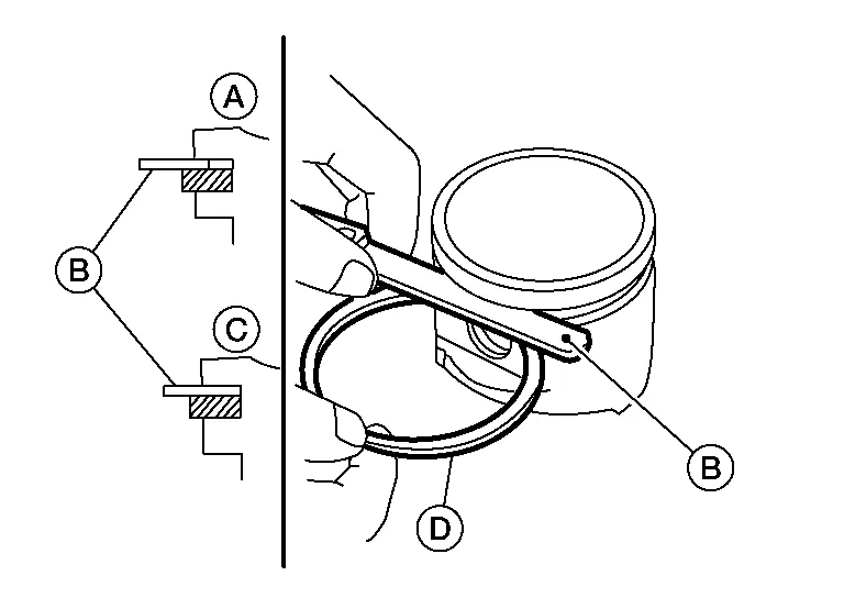
Install the main bearings and the thrust bearings (C).
-
Install the thrust bearings (C) with the oil groove (B) facing the crankshaft arm (outside).
-
Install bearing with a projection on one end on cylinder block and bearing with a projection at center on cap. Align each projection with mating notch.
| : Engine front |
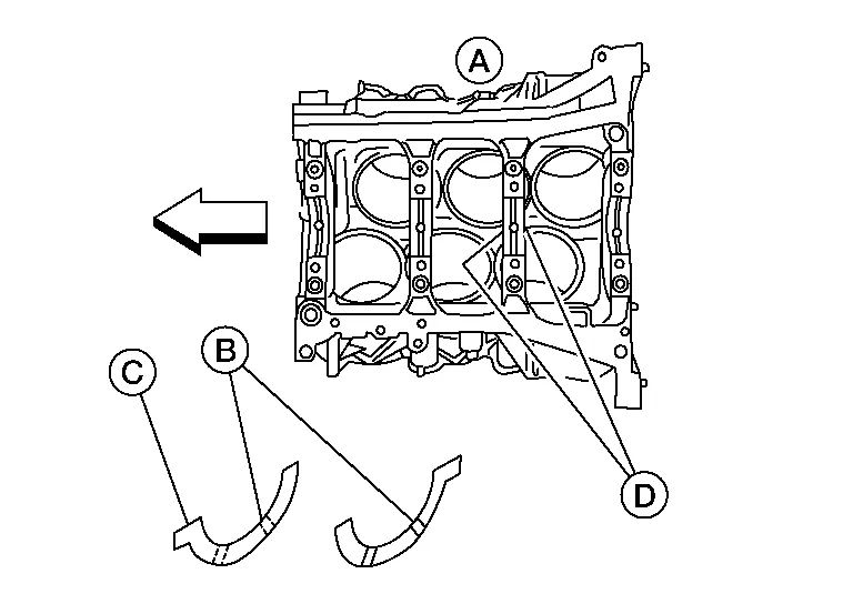
Set the upper main bearings (A) and the lower main bearings (B) in their proper positions on the cylinder block.
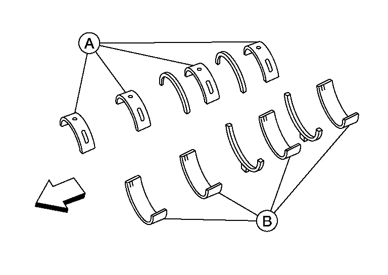
-
Confirm the correct main bearings are used. Refer to Inspection.
NOTE:
The upper main bearings (A) have an oil groove. The lower main bearings do not have an oil groove.
| : Engine front |
Instructions for the reuse of the main bearing cap bolts.

-
A plastic zone tightening method is used for tightening the main bearing cap bolts. Measure (d1) and (d2) as shown.
-
For (d2), select the minimum diameter in the measuring area.
-
If the difference between (d1) and (d2) exceeds the limit, replace the bolts for assembly.
| Limit (d1 - d2) | : 0.11 mm (0.0043 in) |
After installing the crankshaft, lower main bearings, main bearing caps, main bearing beam, and bearing cap bolts. Tighten the bearing cap bolts in the numerical order as shown.
CAUTION:
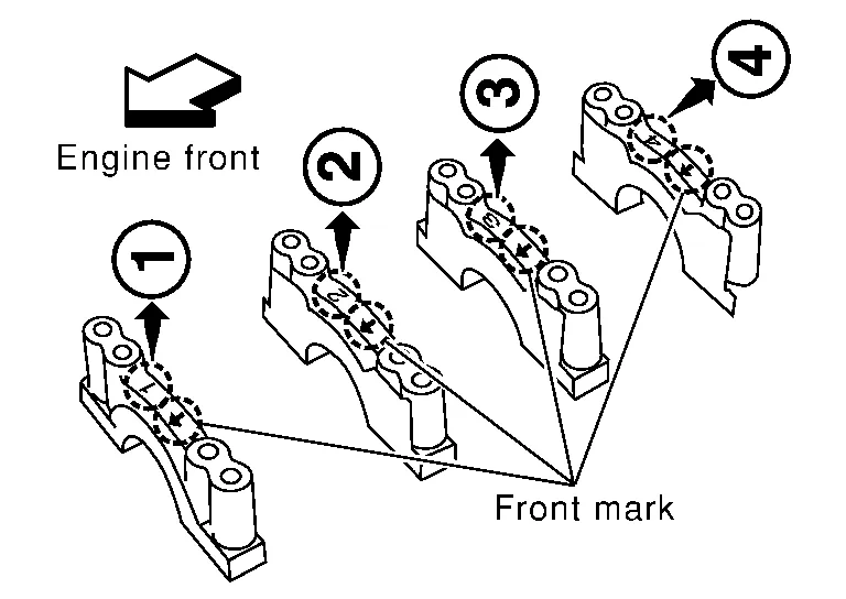
Position main bearing caps in accordance with the numerical stamp.
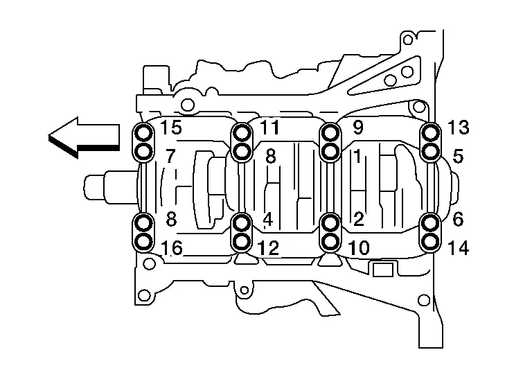
| : Engine front |
CAUTION:
Measure the tightening angle in two stages using Tool (A). Do not measure with eyes only, be sure to use Tool (A).
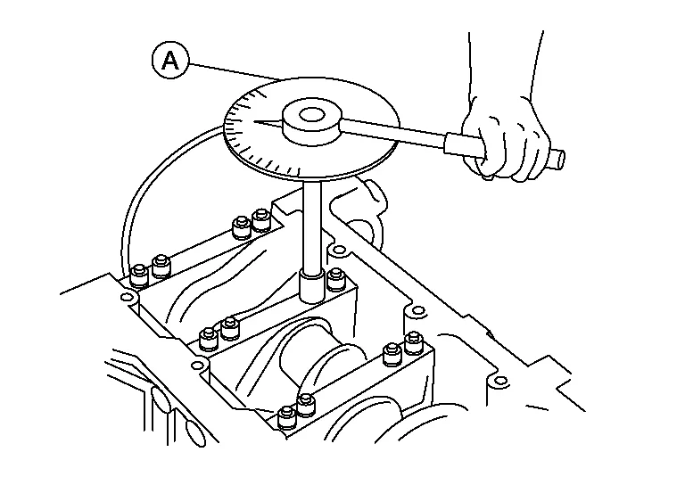
| Stage 1 | : 32.3 - 38.3 N·m (3.3 - 3.9 kg-m, 24 - 28 ft-lb) |
| Stage 2 | : 90° - 95° degrees clockwise |
| Tool number (A) | : KV10112100 (BT-8653-A) |
Measure crankshaft end play.
-
If beyond the limit, replace the thrust bearing with a new one. Refer to Cylinder Block.
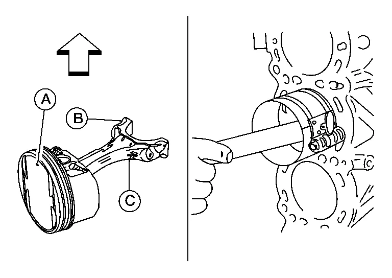
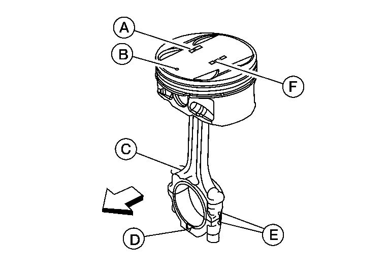
Install the piston to the connecting rod.

CAUTION:
Do not reuse snap rings.
| (A) | : Piston front mark |
| (B) | : Oil hole |
| (C) | : Connecting rod front mark |
| (D) | : Cylinder No. |
-
Heat the piston using suitable tool (A) until the piston pin can be pushed in by hand without excess force [approximately 60 - 70°C (140 - 158°F)]. From the front to the rear, insert the piston pin into the piston and through the connecting rod.
WARNING:
Pistons contain heat. When working, wear protective equipment to avoid getting burned.
-
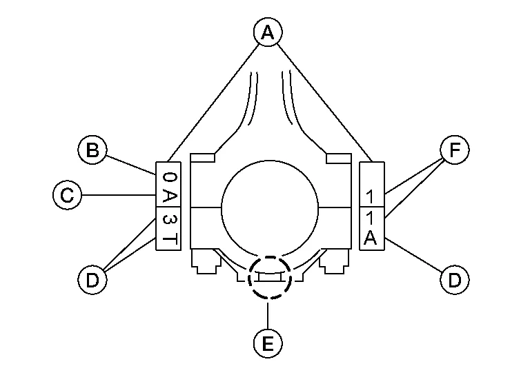
Assemble so that the piston front mark (B) on the crown and the oil hole (C), connecting rod front mark (D) and Cylinder No. (E) on the connecting rod are positioned as shown.
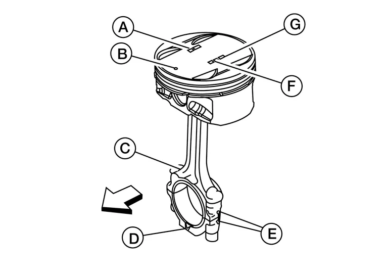
: Engine front (A) : Piston grade number (F) : Pin grade number (G) : Crown I.D. code
-
After installing, check that the connecting rod pivots smoothly on the pin.
CAUTION:
Do not reuse snap rings, always replace with new ones.
Using a piston ring expander, install the piston rings.
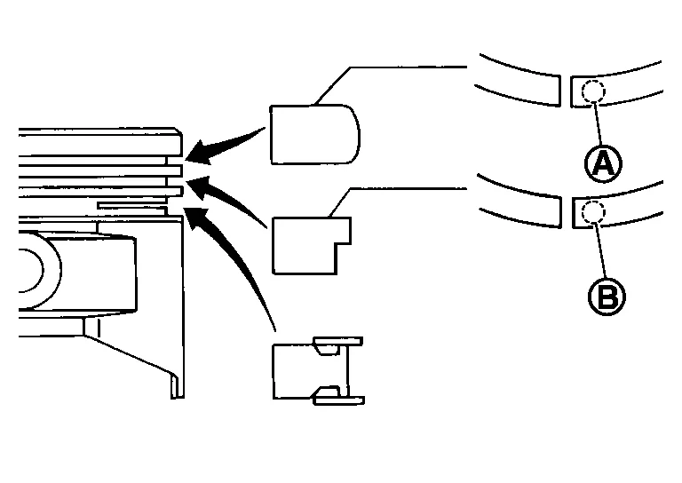
| (A) | : Top ring |
| (B) | : Second ring |
CAUTION:
-
Be careful not to damage the piston.
-
When the piston rings are not replaced, remount the rings in their original positions.
-
When replacing the piston rings, those without stamped surface (A) can be mounted either side up.
-
Install the second ring with the stamped surface (B) facing upward. If the ring is not stamped it can face in either direction.
-
Position each ring with the gap as shown, referring to the piston front mark.
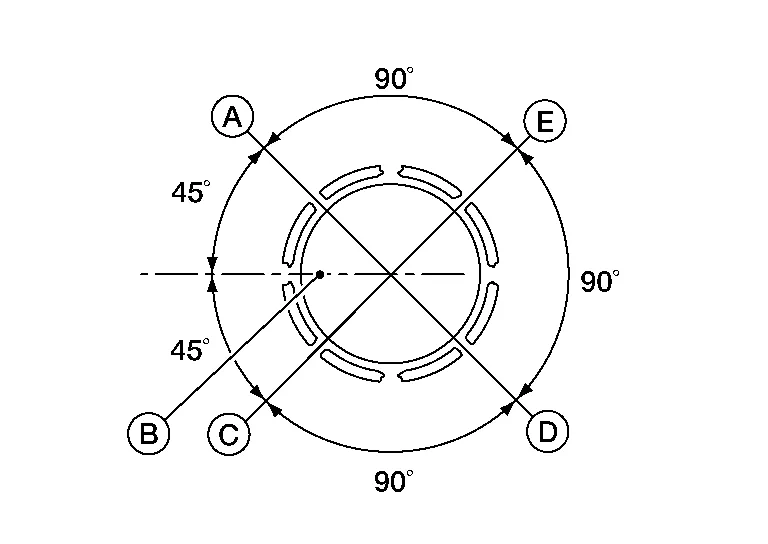
(A) : Top ring gap (B) : Front mark (C) : Oil ring upper or lower rail gap (D) : Second ring and oil ring spacer gap (E) : Oil ring upper or lower rail gap
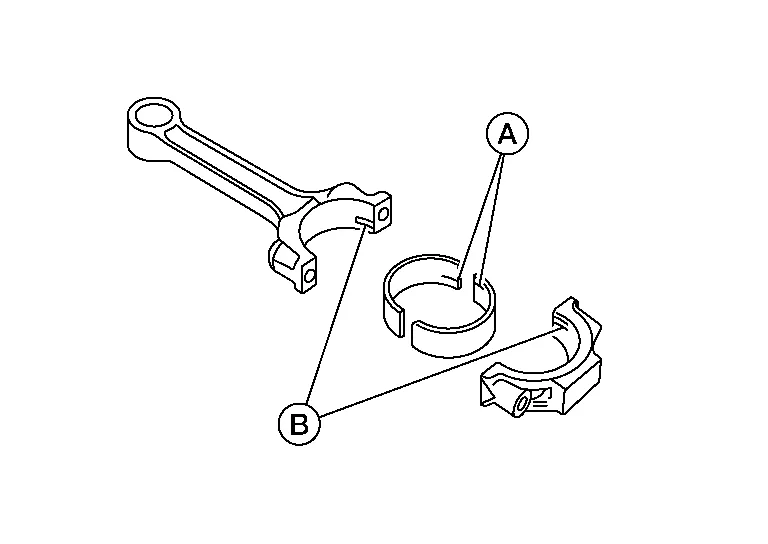
Install the connecting rod bearings (A) to the connecting rod and the connecting rod cap (B).
-
When installing the connecting rod bearings (A), apply engine oil to the bearing surface (crankshaft side). Do not apply oil to the back surface (connecting rod and cap side), but thoroughly clean it.
-
When installing, align the connecting rod bearing (A) protrusion with the notch of the connecting rod to install.
-
Check that the oil holes on the connecting rod (B) and on the corresponding bearing (A) are aligned.
Install the piston and connecting rod assembly into the corresponding cylinder.
-
Position the crankshaft pin corresponding to the connecting rod to be installed onto the bottom dead center.
-
Apply engine oil sufficiently to the cylinder bore, piston, and crankshaft pin.
-
Match the cylinder position with the cylinder No. (B) on the connecting rod to install.
-
Install the piston with the piston front mark (A) on the crown facing the front of the engine (
) using a suitable tool.(C) : Oil hole
CAUTION:
Be careful not to damage the crankshaft pin and cylinder wall, resulting from interference of the connecting rod big end.
Install the connecting rod cap.
-
Observing the sample codes (A), match the stamped cylinder number marks (F) on the connecting rod with those on the cylinder cap for installation.
-
Install the piston connecting rod assembly and cap so that the front mark on the cap and piston are facing the front of the engine.
-
Lubricate the threads and seat surfaces with new engine oil.
| (B). | : Small end diameter grade |
| (C). | : Weight grade |
| (D). | : Management code |
| (E). | : Front mark |
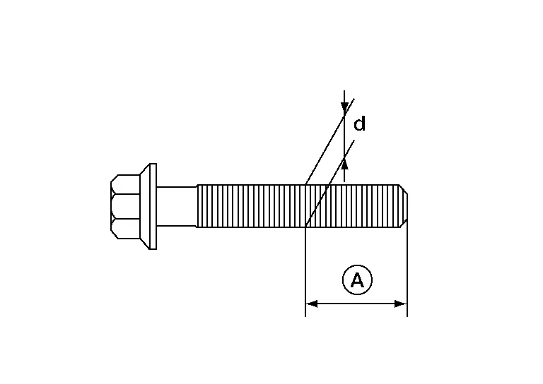
Check the connecting rod cap bolts before reusing, then install in their original position in the connecting rod. The bolts should screw in smoothly by hand.
-
Measure the outer diameter of the connecting rod cap bolt as shown.
| Outer diameter (d) of the connecting rod bolt | |
| Standard | : 7.90 - 8.00 mm (0.3110 - 0.3150 in) |
| Limit | : 7.75 mm (0.3051 in) |
| (A) | : 19 mm (0.75 in) |
Tighten the connecting rod nuts in two stages using Tool:
| Stage 1 | : 19 - 21 N·m (1.9 - 2.1 kg-m, 14 - 15 ft-lb) |
| Stage 2 | : 90° - 95° degrees clockwise |
CAUTION:
Always use either an angle wrench or protractor. Avoid tightening based on visual check alone.
| Tool number | : KV10112100 (BT-8653-A) |
-
Apply engine oil to the threads and seats of the connecting rod bolts and nuts.
-
After tightening the nuts, make sure that the crankshaft rotates smoothly.
-
Check the connecting rod side clearance. If beyond the limit, replace the connecting rod and/or crankshaft. Refer to Cylinder Block.
Install the baffle plate to the main bearing beam.
Install the knock sensor (A).
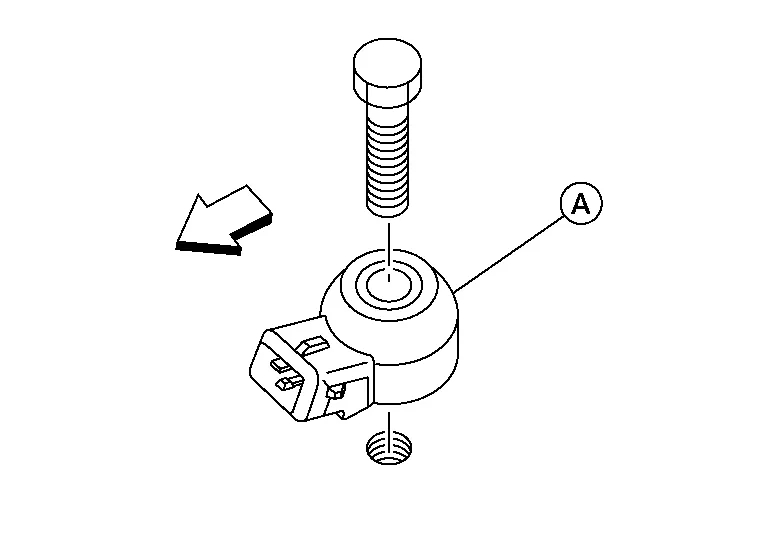
-
Make sure that there is no foreign material on the cylinder block mating surface and the back surface of the knock sensor (A).
-
Install the knock sensor (A) with the connector facing the rear of the engine.
-
Do not tighten the bolts while holding the connector.
-
Make sure that the knock sensor (A) does not interfere with other parts.
| : Engine front |
CAUTION:
If any impact by dropping occurs to the knock sensor (A), replace it with new one.
Install the cylinder head. Refer to Removal and Installation.
Install the timing chain. Refer to Removal and Installation.
Install the oil pan. Refer to Removal and Installation (Lower Oil Pan) and Removal and Installation (Upper Oil Pan).
Remove the engine from the stand.
Install the pilot converter with its chamfer facing crankshaft as shown.
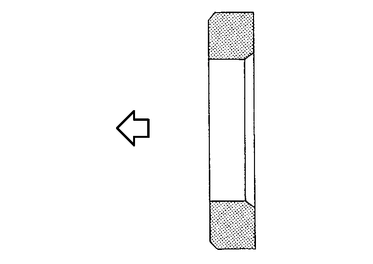
| : Crankshaft side |
Install the rear oil seal using Tool (A).

| Tool number (A) | : — (J-47128) |

Use Genuine Silicone RTV Sealant, or equivalent. Refer to Recommended Chemical Products and Sealants.
CAUTION:
-
Installation should be done within 5 minutes after applying liquid gasket.
-
Do not fill the engine with oil for at least 30 minutes after the components are installed to allow the sealant to cure.

Install the drive plate. Refer to Exploded View.
Install the engine assembly into the Nissan Murano vehicle. Refer to Removal and Installation (FWD) or Removal and Installation (AWD).
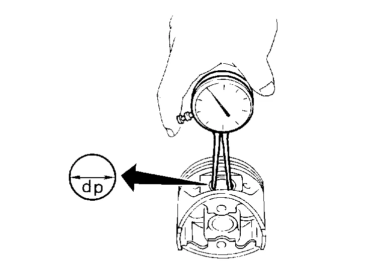
PISTON AND PISTON PIN CLEARANCE
Inner Diameter of Piston Pin Hole
-
Measure the inner diameter of piston pin hole (dp). Refer to Cylinder Block.
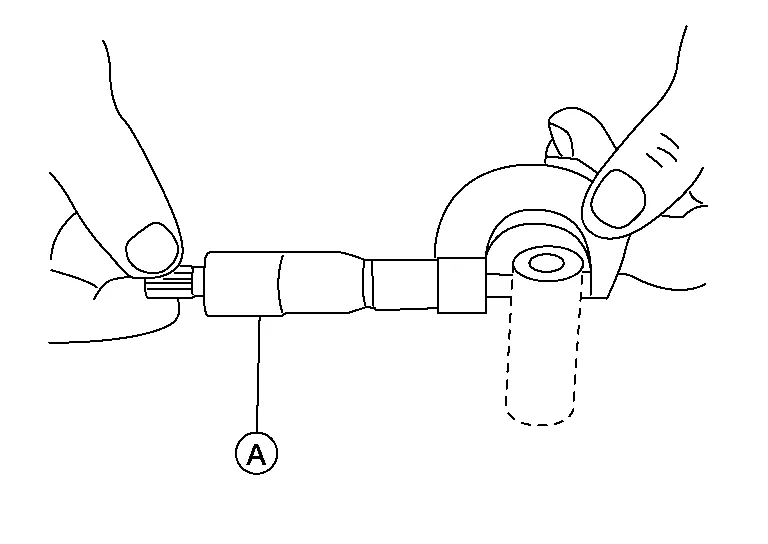
Outer Diameter of Piston Pin
-
Measure outer diameter of piston pin (Dp) using suitable tool (A). Refer to Inspection.
| : Engine front | |
| (A) | : Piston Grade No. |
| (B) | : Piston front mark |
| (C) | : Oil hole |
| (D) | : Connecting rod front mark |
| (E) | : Cylinder No. |
| (F) | : Pin Grade No. |
Piston and Piston Pin Interference Fit
Standard Interference Fit = (Dp) – (dp)
| Standard | : 0.002 – 0.010 mm (0.0001 – 0.0004 in) |
-
If clearance exceeds specification, replace either or both of piston/piston pin assembly and connecting rod assembly with reference to specification of each part.
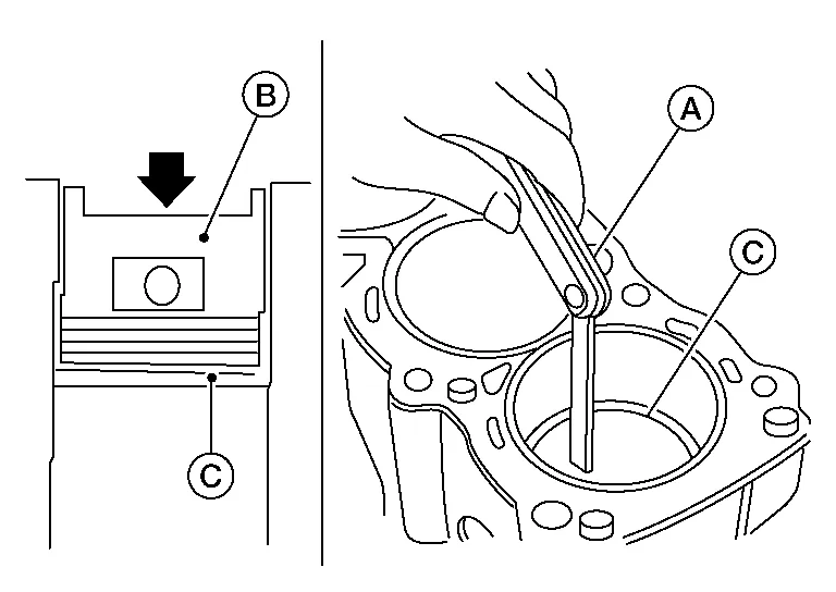
PISTON RING SIDE CLEARANCE
-
Measure side clearance of piston ring and piston ring groove with suitable tool (B).
-
If out of specification, replace piston ring assembly (D). If clearance exceeds maximum limit with new rings, replace piston. Refer to Cylinder Block.
| (A) | : NG |
| (C) | : OK |
PISTON RING END GAP
-
Insert piston ring (C) until it is in the middle of the cylinder bore and measure the end gap using suitable tool (A).
-
If out of specification, replace piston ring (C). Refer to Cylinder Block.
| (B) | : Piston Press Fit |
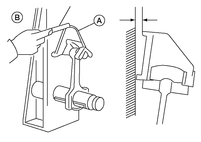
CONNECTING ROD BEND AND TORSION
-
Use suitable tool (A) to measure bend (B) and torsion (B).
-
If bend (B) or torsion (B) exceeds the limit, replace connecting rod assembly. Refer to Connecting Rod Bearing.
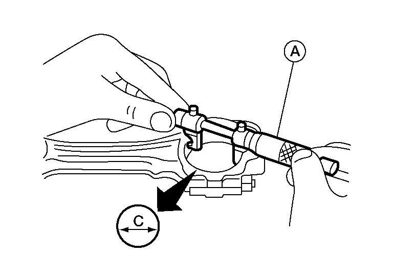
CONNECTING ROD BEARING HOUSING DIAMETER (BIG END)
-
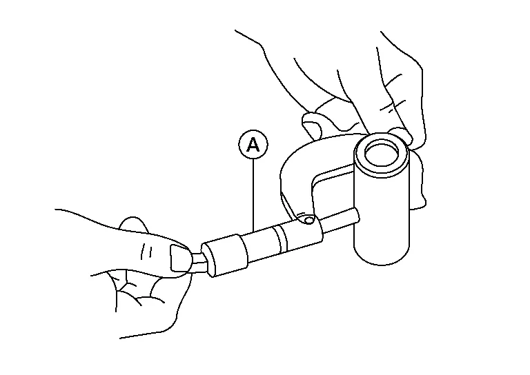
Install the connecting rod cap without the connecting rod bearing installed. After tightening the connecting rod nut to the specified torque, measure the connecting rod bearing housing big end inner diameter using a suitable tool (A). Refer to Connecting Rod Bearing.
CONNECTING ROD BUSHING OIL CLEARANCE (SMALL END)
Inner Diameter of Connecting Rod (Small End)
-
Measure inner diameter of piston pin bushing using a suitable tool (A). Refer to Connecting Rod Bearing.
Outer Diameter of Piston Pin
-
Measure outer diameter of piston pin using suitable tool (A). Refer to Cylinder Block.
Connecting Rod Bushing Oil Clearance (Small End)
(Connecting rod small end oil clearance) = (Inner diameter of connecting rod small end) – (Outer diameter of piston pin). Refer to Cylinder Block.
-
If the measured value exceeds the standard, replace the connecting rod assembly and/or piston and piston pin assembly.
-
If replacing the piston and piston pin assembly, use the Table for Selective Fitting for Piston to select the piston corresponding to the applicable bore grade of the cylinder block to be used. Follow the "PISTON-TO-CYLINDER BORE CLEARANCE" procedure.
| (A) | : Sample codes |
| (B) | : Small end diameter grade |
| (C) | : Weight grade |
| (D) | : Management code |
| (E) | : Front mark |
| (F) | : Cylinder number |
Factory installed parts grading:
| : Engine front | |
| (A) | : Piston Grade No. |
| (B) | : Piston front mark |
| (C) | : Oil hole |
| (D) | : Connecting rod front mark |
| (E) | : Cylinder No. |
| (F) | : Pin Grade No. |
| (G) | : Crown I.D. code |
Service parts apply only to grade 0.
Unit: mm (in)
| Grade | 0 | 1 |
| Connecting rod small end inner diameter |
22.000 - 22.006 (0.8661 - 0.8664) |
22.006 - 22.012 (0.8664 - 0.8666) |
| Piston pin outer diameter |
21.989 - 21.995 (0.8657 - 0.8659) |
21.995 - 22. 001 (0.8659 - 0.8662) |
| Piston pin hole diameter |
21.993 - 21.999 (0.8659 - 0.8661) |
21.999 - 22.005 (0.8661 - 0.8663) |
CYLINDER BLOCK DISTORTION
-
Using a scraper, remove any old gasket material on the cylinder block surface and remove any oil, scale, carbon, or other contamination.

CAUTION:
Be careful not to allow gasket flakes to enter the oil or coolant passages.
-
Using suitable tools (A/B), measure the distortion on the block upper face at different points in six directions. Refer to Cylinder Block.
-
If out of specification, resurface the cylinder block. The allowable amount of resurfacing is dependent on the amount of any cylinder head resurfacing. The resurfacing limit is [amount of cylinder head resurfacing] + [amount of cylinder head resurfacing] = 0.2 mm (0.008 in).
Cylinder block height : 214.95 - 215.05 mm (8.4626 - 8.4665 in)
INNER DIAMETER OF MAIN BEARING HOUSING
-
Install the main bearing caps with the main bearings removed, and tighten the bolts to the specified torque.
-
Using a bore gauge, measure the inner diameter of the main bearing housing (A). Refer to Cylinder Block.
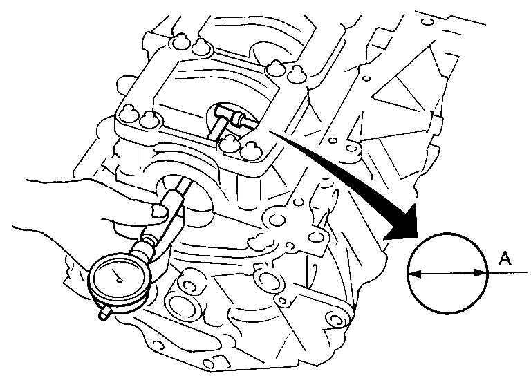
-
If out of the standard, replace the cylinder block and main bearing caps as an assembly.
NOTE:
These components cannot be replaced as a single unit, because they were processed together.
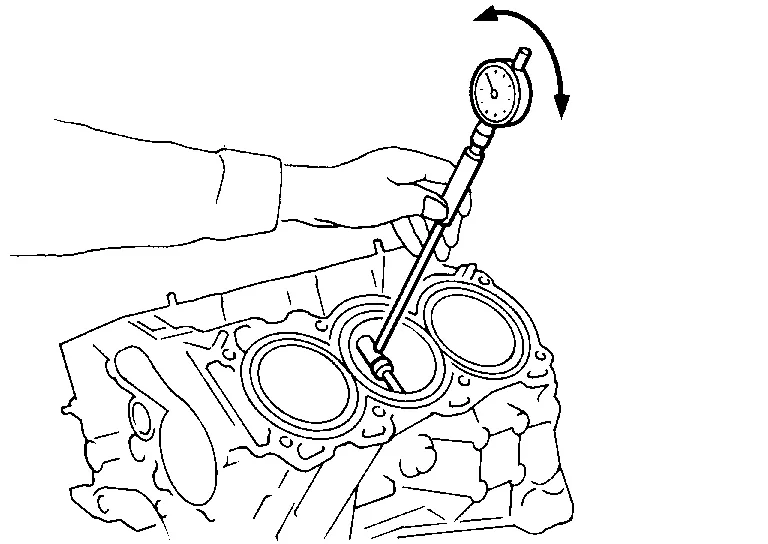
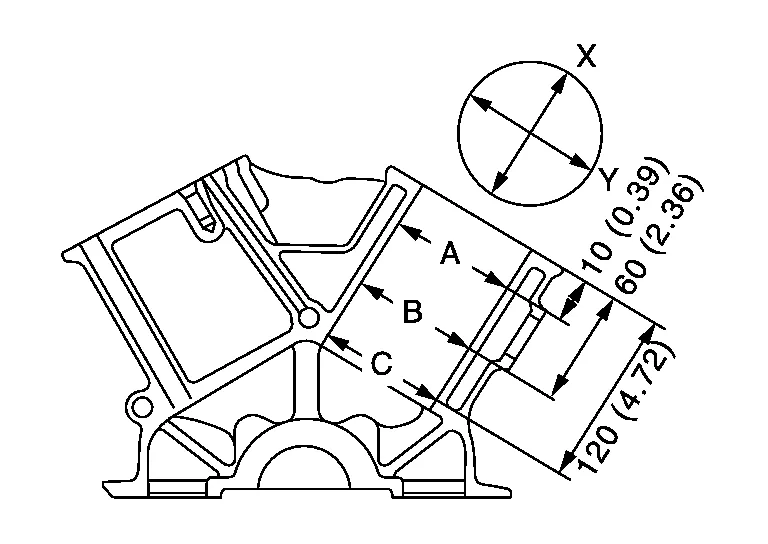
PISTON-TO-CYLINDER BORE CLEARANCE
Using a bore gauge, measure cylinder bore for wear, out-of-round and taper at (A), (B) and (C). The X axis is in the longitudinal direction of the engine.
| Grade No. | Standard inner diameter | Wear limit |
|---|---|---|
| No. 1 | 95.500 - 95.510 mm (3.7598 - 3.7602 in) | 0.20 mm (0.0079 in) |
| No. 2 | 95.510 - 95.520 mm (3.7602 - 3.7606 in) | |
| No. 3 | 95.520 - 95.530 mm (3.7606 - 3.7610 in) |
If it exceeds the limit, rebore all cylinders. Replace cylinder block if necessary. Refer to Cylinder Block.
Check for scratches and seizure. If seizure is found, hone it.
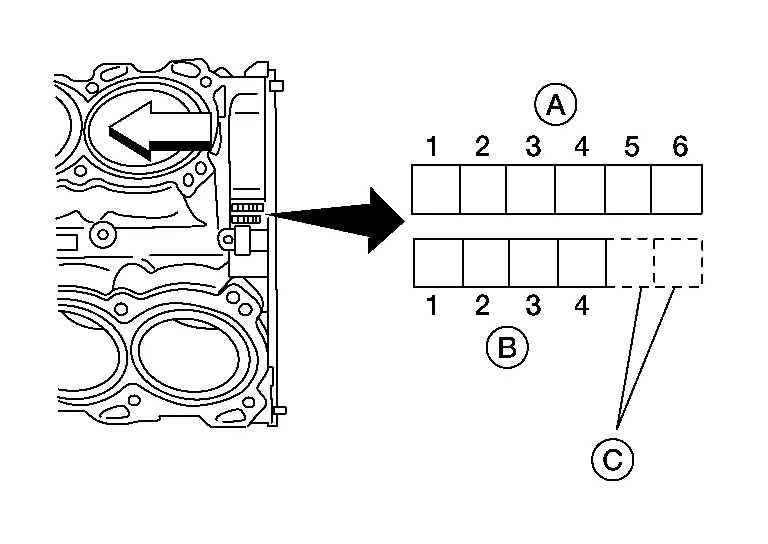
-
If both cylinder block and piston are replaced with new ones, select piston of the same grade number punched on cylinder block rear position. These numbers are punched in either Arabic or Roman numerals.
| (A) | : Cylinder bore grade |
| (B) | : Small end diameter grade |
| (C) | : Management code |
| : Engine front |
Measure piston skirt diameter. Refer to Cylinder Block.
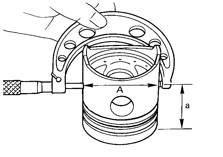
Check that piston-to-bore clearance is within specification. Refer to Cylinder Block.
-
The piston-to-bore clearance is measured at the (B) level in the cylinder as shown.
Cylinder bore size is determined by adding piston-to-bore clearance to piston diameter (A).
| Rebored size calculation | : D = A + B − C |
| where, | |
| (D) | : Bored diameter |
| (A) | : Piston diameter as measured |
| (B) | : Piston-to-bore clearance |
| (C) | : Honing allowance 0.02 mm (0.0008 in) |
Install main bearing caps, and tighten to the specified torque. Otherwise, cylinder bores may be distorted after boring.
Cut cylinder bores.
-
When any cylinder needs boring, all other cylinders must also be bored.
-
Do not cut too much out of cylinder bore at a time. Cut only 0.05 mm (0.0020 in) or so in diameter at a time.
Hone cylinders to obtain specified piston-to-bore clearance.
Measure finished cylinder bore for out-of-round and taper.
-
Measurement should be done after cylinder bore cools down.
CRANKSHAFT
Check the crankshaft main and pin journals for scoring, wear, or cracks.
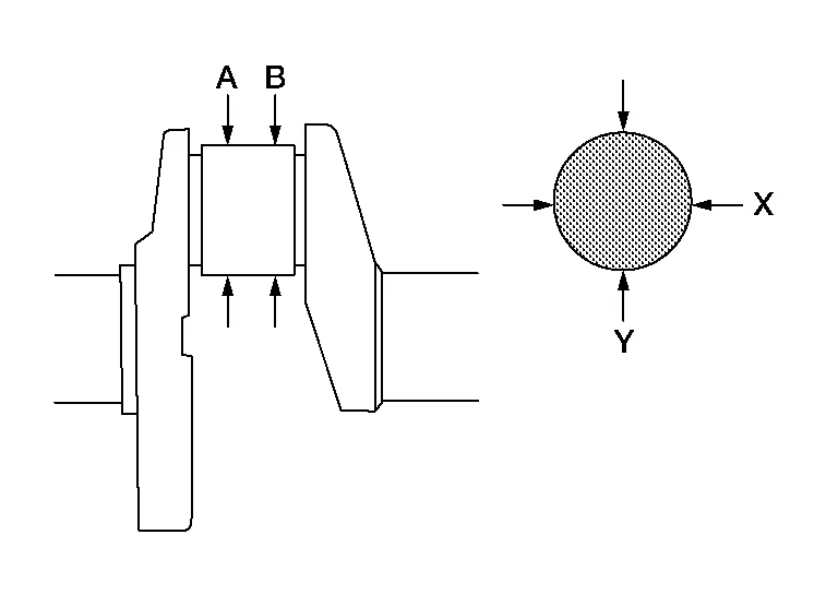
Measure the journals for taper and out-of-round. Refer to Cylinder Block.
| Taper | : A - B |
| Out-of-round | : X - Y |
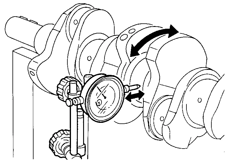
Measure crankshaft runout.
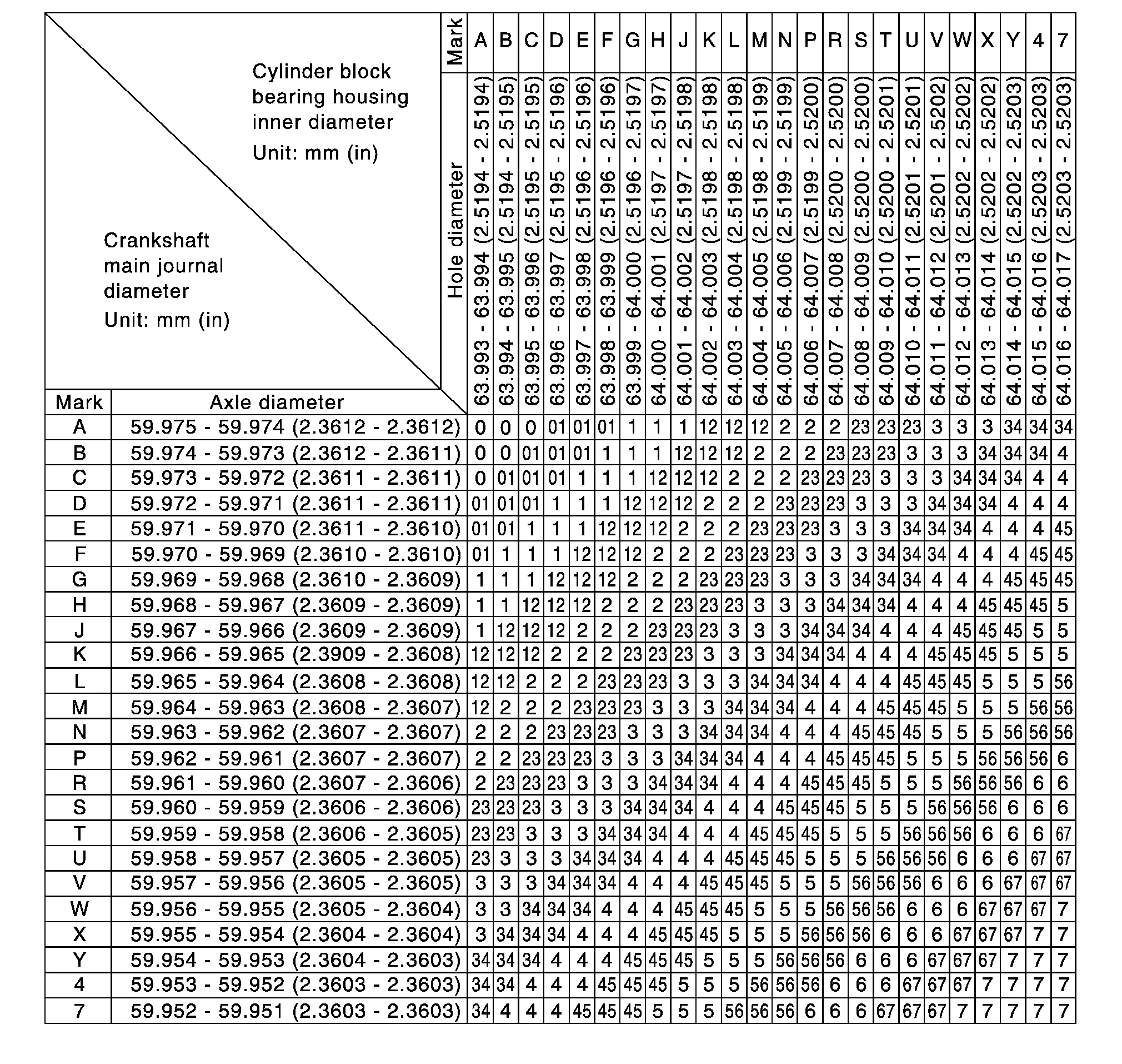
BEARING CLEARANCE
-
Use either of the following two methods, however method (A) gives more reliable results and so is the preferred method.
Method A (Using Bore Gauge and Micrometer)
Main Bearing
Set the upper main bearings (A) and the lower main bearings (B) in their proper positions on the cylinder block.
-
Confirm the correct main bearings are used. Refer to Inspection.
NOTE:
The upper main bearings (A) have an oil groove. The lower main bearings do not have an oil groove.
| : Engine front |
Install the main bearing caps and bearing beam to the cylinder block. Tighten all bolts in the numerical order as specified. Refer to Disassembly and Assembly.
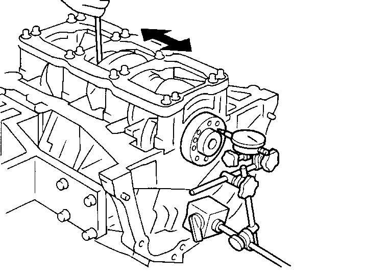
Measure the inner diameters (A) of each main bearing as shown.
Measure the outer diameters (Dm) of each crankshaft main journal as shown.

Calculate the main bearing clearance. Refer to Main Bearing.
-
If it exceeds the limit, replace the bearing.
-
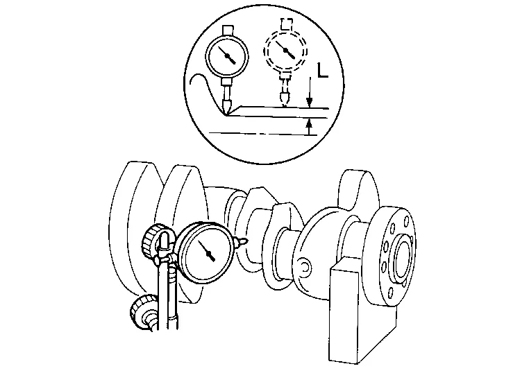
If clearance cannot be adjusted using any standard bearing grade, grind crankshaft journal and use an undersized bearing.
-
When grinding the crankshaft journal, confirm that the (L) dimension in the fillet role is more than the specified limit. Refer to Cylinder Block.
If the crankshaft or the cylinder block is replaced with a new one, select thickness of the main bearings as follows:The grade number of each cylinder block main journal is punched on the respective cylinder block. These numbers are punched in either Arabic or Roman numerals. If measured diameter is out of the grade punched, decide suitable grade from available main bearings.
| (A) | : Cylinder bore grade |
| (B) | : Small end diameter grade |
| (C) | : Management code |
| : Engine front |

| (A) | : Journal diameter grade |
| (B) | : Identification code |
| (C) | : Pin diameter grade |
Connecting Rod Bearing (Big End)
Install the connecting rod bearing to the connecting rod and cap.
Install the connecting rod cap to the connecting rod. Tighten to specification. Refer to Disassembly and Assembly.
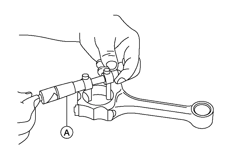
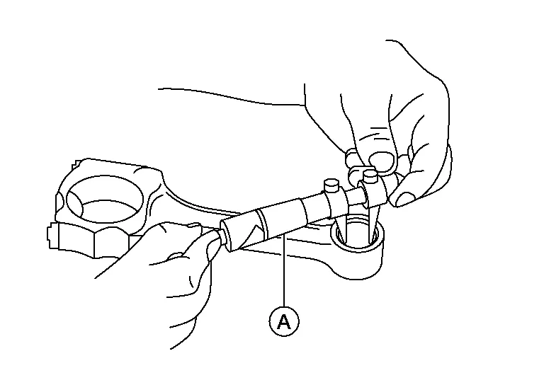
Measure the inner diameter (C) of each connecting rod (big end) using suitable tool (A) as shown.
Measure the outer diameter (Dp) of each crankshaft pin journal.

Calculate the connecting rod bearing clearance. Refer to Connecting Rod Bearing.
Connecting rod bearing clearance = (C) - (Dp)
If the calculated clearance exceeds the specified limit, replace the bearings.
If the clearance cannot be adjusted within the standard of any bearing, grind the crankshaft journal and use undersized bearings.
If the crankshaft is replaced with a new one, select the connecting rod bearings according to the following table:
Connecting Rod Bearing Grade Number (Identification Color)
| Crankshaft pin journal grade number | Connecting rod bearing grade number |
|---|---|
| 0 | 0 (black) |
| 1 | 1 (brown) |
| 2 | 2 (green) |
These numbers are punched in either Arabic or Roman numerals.
| (A) | : Journal diameter grade |
| (B) | : Identification code |
| (C) | : Pin diameter grade |
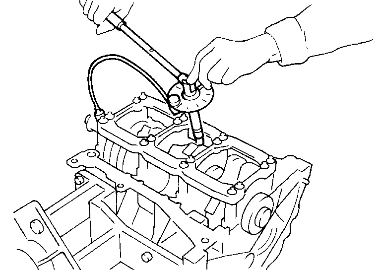
Method B (Using Plastigage)
-
Remove oil and dust on the crankshaft pin and the surfaces of each bearing completely.
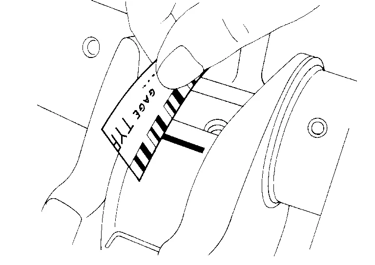
-
Cut a Plastigage slightly shorter than the bearing width, and place it in crankshaft axial direction, avoiding oil holes.
-
Install the connecting rod bearings to the connecting rod cap, and tighten the connecting rod nuts to the specified torque.
CAUTION:
Do not rotate the crankshaft.
-
Remove the connecting rod cap and bearings, and using the scale on the Plastigage bag, measure the Plastigage width.
NOTE:
The procedure when the measured value exceeds the repair limit is same as that described in "Method A (Using Bore Gauge and Micrometer)".
DRIVE PLATE RUNOUT
Use dial gauge to measure the runout (Total Indicator Reading) as shown. Refer to Drive Plate.
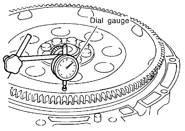
CAUTION:
-
The signal plate is built into the drive assembly. Be careful not to damage the signal plate, particularly the teeth.
-
Check the drive plate and signal plate for deformation or cracks.
-
Keep all magnetized objects away from the signal plate, particularly the teeth.
OIL JET
-
Check nozzle for deformation and damage.
-
Blow compressed air from nozzle, and check for clogs.
-
If it is not operating properly, replace oil jet.
OIL JET RELIEF VALVE
-
Using a clean plastic stick, press check valve in oil jet relief valve. Make sure that valve moves smoothly with proper reaction force.

-
If it is not operating properly, replace oil jet relief valve.
REMOVAL
-
Use suitable tool to lock the drive plate and match mark (A) the drive plate before removing the bolts.

CAUTION:
Do not damage the ring gear teeth or the signal plate teeth behind the ring gear.
-
Remove drive plate.
-
Loosen the drive plate in a diagonal order.
CAUTION:
-
Do not place drive plate with signal plate facing down.
-
When handling the signal plate, take care not to damage or scratch it.
-
Handle the signal plate in a manner that prevents it from becoming magnetized.
-
INSTALLATION
Installation is in the reverse order of removal.
-
When installing the drive plate to the crankshaft, use the match mark (A) as shown to correctly align the crankshaft side dowel pin to the drive plate side dowel pin hole.
-
Install the drive plate and the reinforcement plate in the direction as shown.
(A) : Signal plate (B) : Crankshaft (C) : Pilot converter (D) : Reinforcement plate (E) : Rounded (F) : Ring gear Engine front -
Tighten the drive plate bolts to specification in a diagonal pattern. Refer to Exploded View.
-
Use a suitable tool to lock the drive plate.
-
 Awd
Awd
Exploded View
1.
Rear torque rod
2.
Rear torque rod bracket
3.
Engine mounting bracket (RH)
4.
Upper torque rod
5.
Engine mounting insulator (RH)
6...
 Engine Mechanical :: Service Data and Specifications (sds). Service Data and Specifications (sds)
General Specification
GENERAL SPECIFICATIONS Cylinder arrangement
V-6
Displacement cm3 (cu in)
3,498 (213.45)
Bore and stroke mm (in)
96 x 81 (3...
Other information:
Nissan Murano (Z52) 2015-2024 Owners Manual: LDW system operation
Lane Departure Warning (LDW) indicator The LDWsystem provides a lane departure warning function when the vehicle is driven at speeds of approximately 37 mph (60 km/h) and above and the lane markings are clear. When the vehicle approaches either the left or the right side of the traveling lane, the steering wheel will vibrate and the LDW indicator on the instrument panel will blink to alert the driver...
Nissan Murano (Z52) 2015-2024 Service Manual: Precaution. Precautions
Precaution for Supplemental Restraint System (SRS) "AIR BAG" and "SEAT BELT PRE-TENSIONER" The Supplemental Restraint System such as “AIR BAG” and “SEAT BELT PRE-TENSIONER”, used along with a front seat belt, helps to reduce the risk or severity of injury to the driver and front passenger for certain types of collisions...
Categories
- Manuals Home
- Nissan Murano Owners Manual
- Nissan Murano Service Manual
- Checking engine oil level
- Rear bench seat adjustment
- Fuel recommendation
- New on site
- Most important about car
Driver and passenger supplemental knee air bag

Driver’s side
The knee air bag is located in the knee bolster, on the driver’s and passenger’s side. All of the information, cautions and warnings in this manual apply and must be followed. The knee air bag is designed to inflate in higher severity frontal collisions, although it may inflate if the forces in another type of collision are similar to those of a higher severity frontal impact. It may not inflate in certain collisions.

Passenger’s side