Nissan Murano: Engine Mechanical :: Periodic Maintenance / Drive Belt
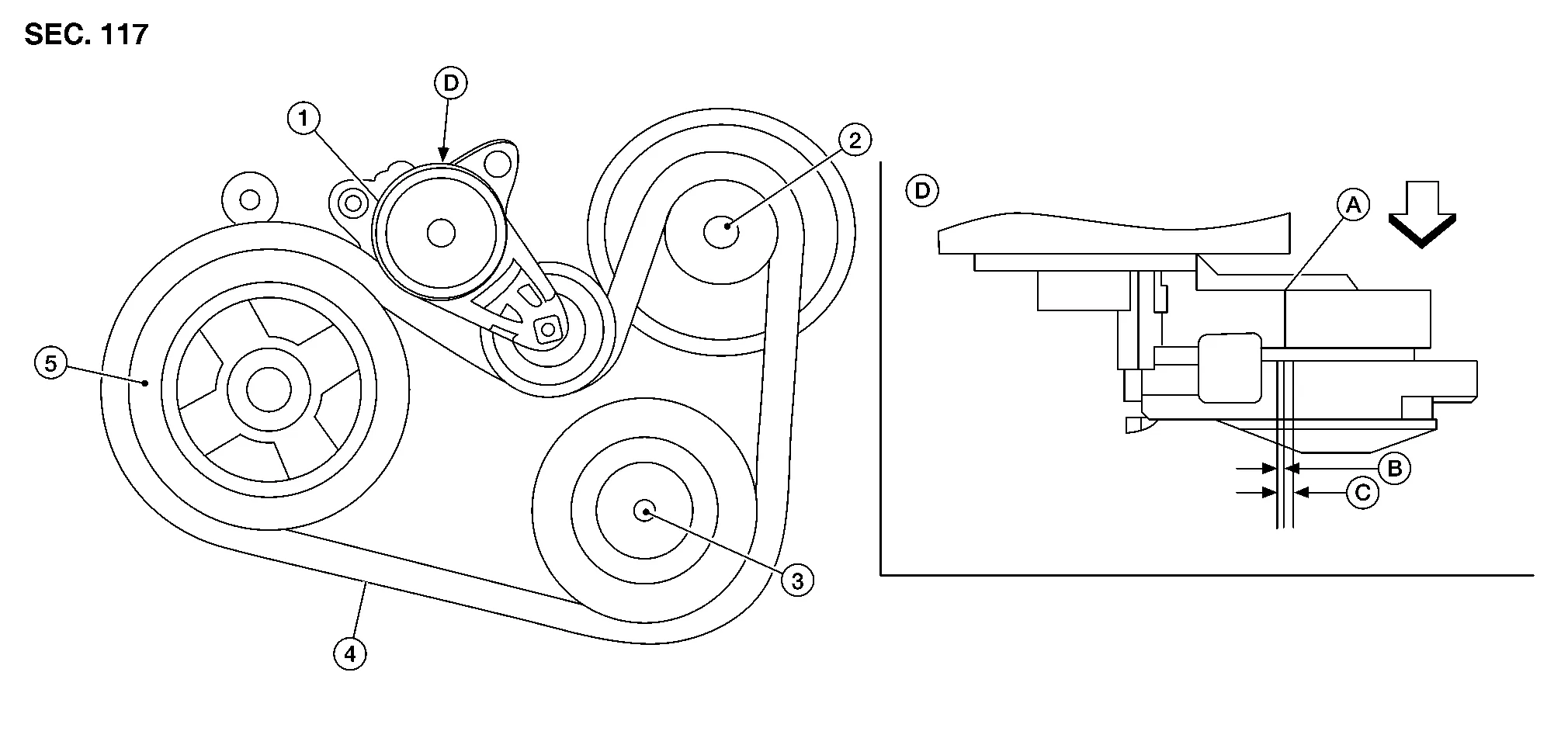
| 1. | Drive belt auto-tensioner | 2. | Generator | 3. | A/C compressor |
| 4. | Drive belt | 5. | Crankshaft pulley | A. | Indicator |
| B. | Range when new drive belt is installed | C. | Possible use range | D. | View D |
| Engine front |
WARNING:
Inspect and check the drive belt with the engine off.
Inspect drive belt for cracks, wear, fraying, or oil adhesion. If necessary, replace with a new one.
Rotate the crankshaft pulley two times, then ensure the drive belt auto-tensioner is within the possible use range.
Visually check entire drive belt for wear, damage or cracks.
Check that the drive belt auto-tensioner indicator is within the possible use range.
 NOTE:
NOTE:
-
When new drive belt is installed, the drive belt auto-tensioner indicator should be within the new drive belt range.
-
Check the drive belt auto-tensioner indicator when the engine is cold.
If the drive belt auto-tensioner indicator is out of the possible use range or belt is damaged, replace drive belt.
-
Drive belt tension is automatically adjusted by the drive belt auto-tensioner.
-
Drive belt tension is not manually adjustable.
REMOVAL
Remove the front wheel and tire (RH) using a power tool. Refer to Removal and Installation.
Remove the fender protector side cover (RH). Refer to Exploded View.
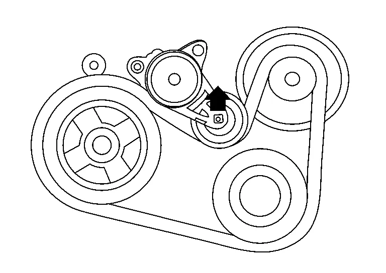
While securely holding the hexagonal part in pulley center of drive belt auto-tensioner, move in the direction of arrow (loosening direction of drive belt auto-tensioner) using suitable tool.
WARNING:
Avoid placing hand in a location where pinching may occur if the holding tool accidentally comes off.
CAUTION:
Do not loosen the drive belt auto-tensioner pulley bolt. (Do not turn it counterclockwise. If turned counterclockwise, the complete drive belt auto-tensioner must be replaced as a unit, including pulley.)
Insert a rod approximately 6 mm (0.24 in) in diameter through the rear of drive belt auto-tensioner into retaining boss to lock drive belt auto-tensioner pulley.
NOTE:
Leave drive belt auto-tensioner pulley arm locked until belt is installed.
Remove drive belt from crankshaft pulley and then remove it from the other pulleys.
INSTALLATION
Install the drive belt onto all of the pulleys.
CAUTION:
Confirm belt is completely set on the pulleys.
Release drive belt auto-tensioner, and apply tension to drive belt.
WARNING:
Avoid placing hand in a location where pinching may occur if the holding tool accidentally comes off.
CAUTION:
Do not loosen the drive belt auto-tensioner pulley bolt. (Don't turn it counterclockwise. If turned counterclockwise, the complete drive belt auto-tensioner must be replaced as a unit, including pulley.)
Turn crankshaft pulley clockwise several times to equalize tension between each pulley.
Confirm drive belt auto-tensioner indicator is within the possible use range. Refer to Checking Drive Belt.
Install the fender protector side cover (RH). Refer to Exploded View.
Install the front wheel and tire (RH). Refer to Removal and Installation.
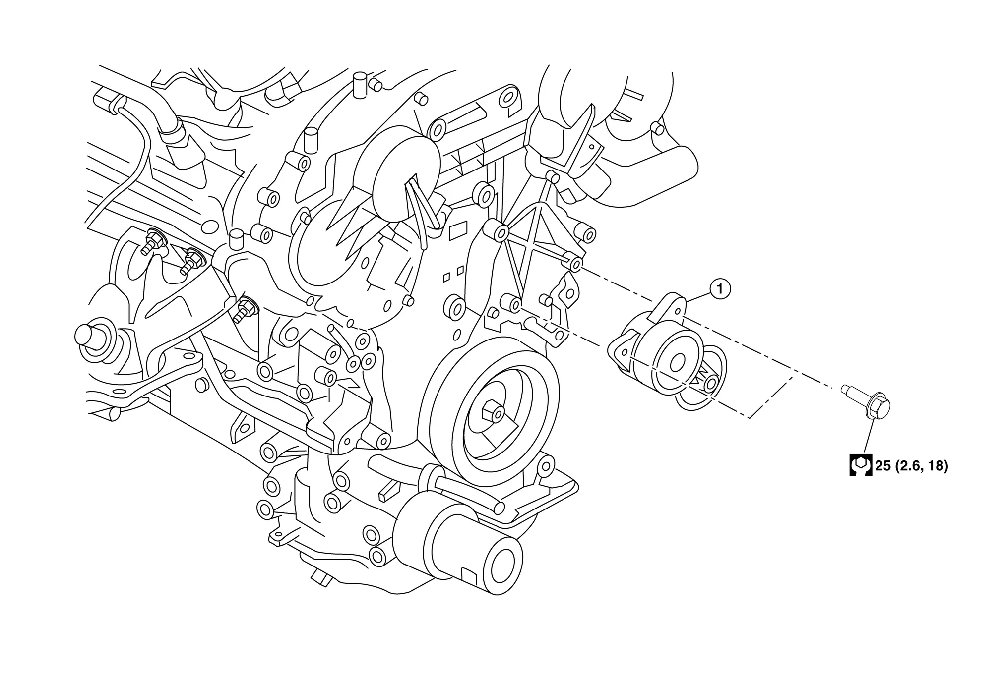
| 1. | Drive belt auto-tensioner |
REMOVAL
CAUTION:
Do not loosen the drive belt auto-tensioner pulley bolt. (Don't turn it counterclockwise. If turned counterclockwise, the complete drive belt auto-tensioner must be replaced as a unit, including pulley).
Remove the drive belt. Refer to Removal and Installation.
Remove the drive belt auto-tensioner.
INSTALLATION
Installation is in the reverse order of removal.
CAUTION:
-
If there is damage greater than peeled paint, replace drive belt auto-tensioner.
-
Do not swap the pulley between the new and old drive belt auto-tensioner.
-
The complete drive belt auto-tensioner must be replaced as a unit, including the pulley.

 Air Cleaner Filter
Exploded View
1.
Air duct hose and resonator assembly
2.
Front air duct
3.
Grommet
4.
Air cleaner case (lower)
5.
Grommets
6.
Air cleaner case mounting bracket
7...
Other information:
Nissan Murano (Z52) 2015-2024 Service Manual: P0315 Crankshaft Position
DTC Description DTC DETECTION LOGIC DTC No. CONSULT screen terms (Trouble diagnosis content) DTC detection condition P0315 Crankshaft position (Crankshaft Position System Variation Not Learned) Diagnosis condition Engine run and fuel shut off Signal — Threshold Learning value of signal plate variation is abnormal or not learned...
Nissan Murano (Z52) 2015-2024 Service Manual: C1a17-49 Icc Sensor
DTC Description DTC DETECTION LOGIC DTC CONSULT screen items (Trouble diagnosis content) DTC detection condition C1A17–49 ICC SENSOR MALF (Distance sensor malfunction) Diagnosis condition When Ignition switch is ON. Signal (terminal) — Threshold If distance sensor is malfunctioning Diagnosis delay time 1 second or less NOTE: If DTC “C1A17–49” is detected along with DTC “U1000–01”, first diagnose the DTC “U1000–01”...
Categories
- Manuals Home
- Nissan Murano Owners Manual
- Nissan Murano Service Manual
- How to enable/disable the LDW system
- All-Wheel Drive (AWD) (if so equipped)
- Settings
- New on site
- Most important about car