Nissan Murano: System Description / Component Parts. Engine Control System
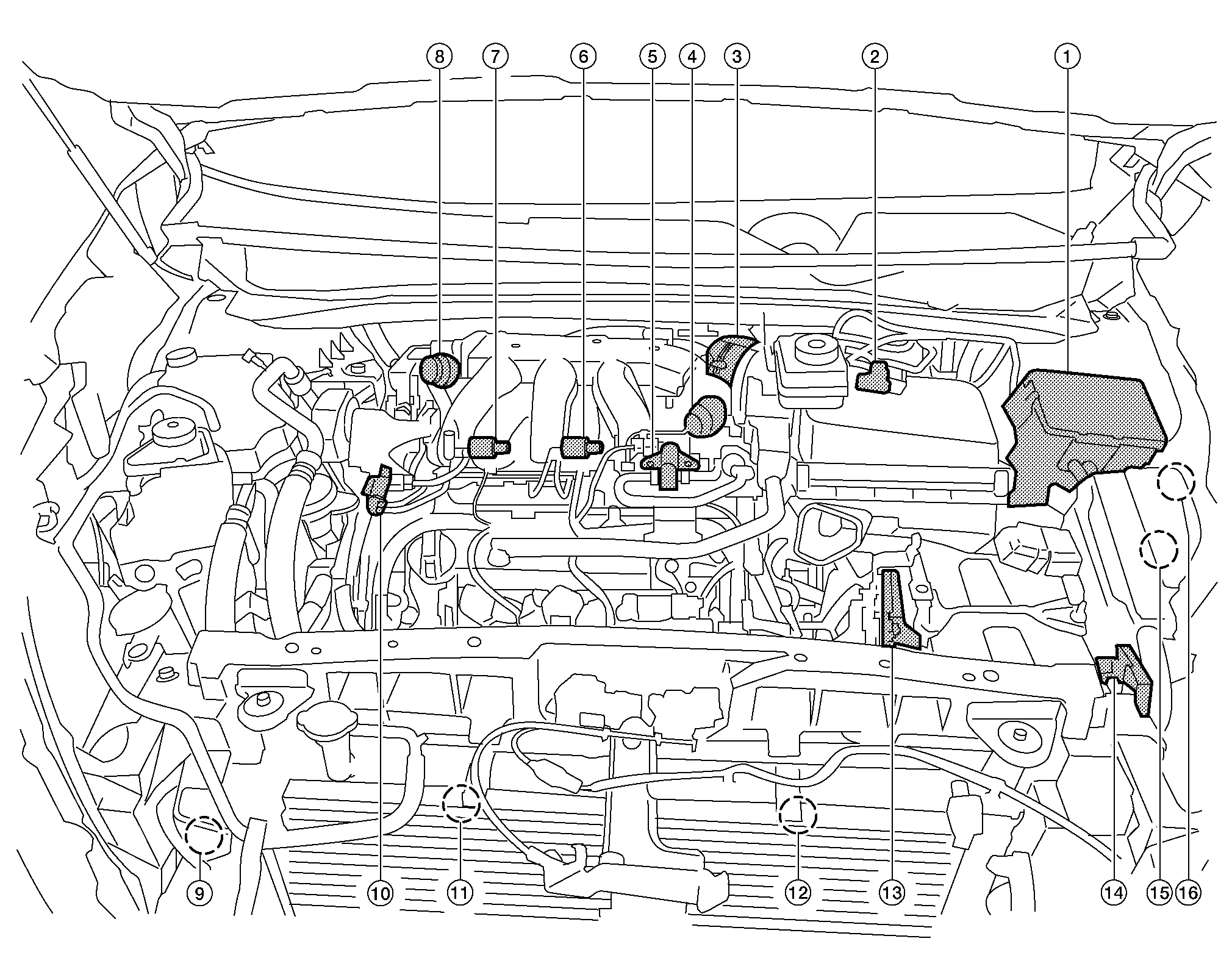
ENGINE ROOM
| No. | Component | Function |
|---|---|---|
 |
IPDM E/R |
IPDM E/R activates the internal control circuit to perform the relay ON-OFF control according to the input signals from various sensors and the request signals received from control units via CAN communication. Refer to Component Parts Location for detailed installation location. |
 |
Mass air flow sensor (with intake air temperature sensor) | Malfunction Indicator Lamp |
 |
Electric throttle control actuator | Electric Throttle Control |
 |
Power valve actuator 2 | Power Valve Actuator 1 and 2 |
 |
EVAP canister purge volume control solenoid valve | EVAP Canister Purge Volume Control Solenoid Valve |
 |
VIAS control solenoid valve 2 | VIAS Control Solenoid Valve 1 and 2 |
 |
VIAS control solenoid valve 1 | VIAS Control Solenoid Valve 1 and 2 |
 |
Power valve actuator 1 | Power Valve Actuator 1 and 2 |
 |
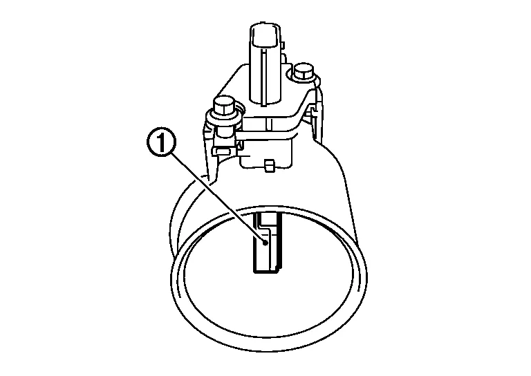
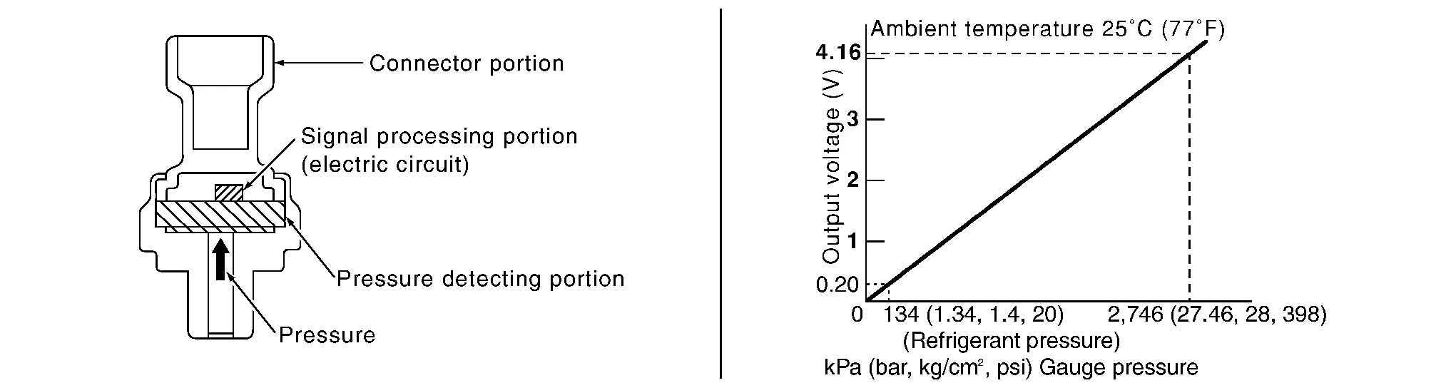
Refrigerant pressure sensor |
Refrigerant Pressure Sensor Refer to Component Parts Location for detailed installation location. |
 |
Electronic controlled engine mount control solenoid valve | Electronic Controlled Engine Mount |
 |
Cooling fan motor-2 | Cooling Fan Motor |
 |
Cooling fan motor-1 | Cooling Fan Motor |
 |
ECM | ECM |
 |
Battery current sensor (with battery temperature sensor)* | — |
 |
Cooling fan relay-2 | — |
 |
Cooling fan relay-3 |
*: Not used for engine control system.
ENGINE
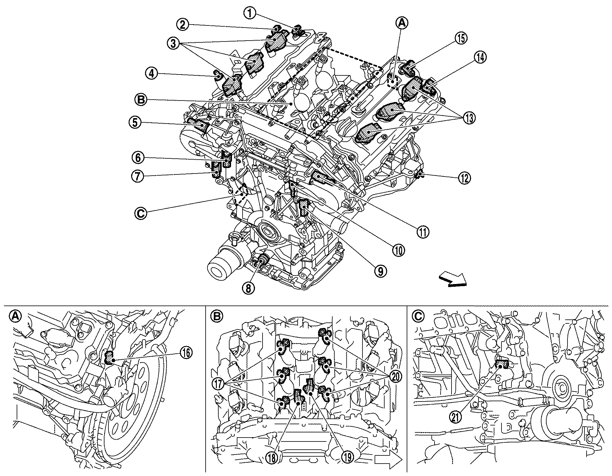
 |
Engine rear upper-left |  |
Engine top center |  |
Engine front lower-right |
| : Nissan Murano Vehicle front |
| No. | Component | Function |
|---|---|---|
|
Camshaft position sensor (PHASE) (bank 1) | Camshaft Position Sensor (PHASE) |
|
Exhaust valve timing control position sensor (bank 1) | Exhaust Valve Timing Control Position Sensor |
|
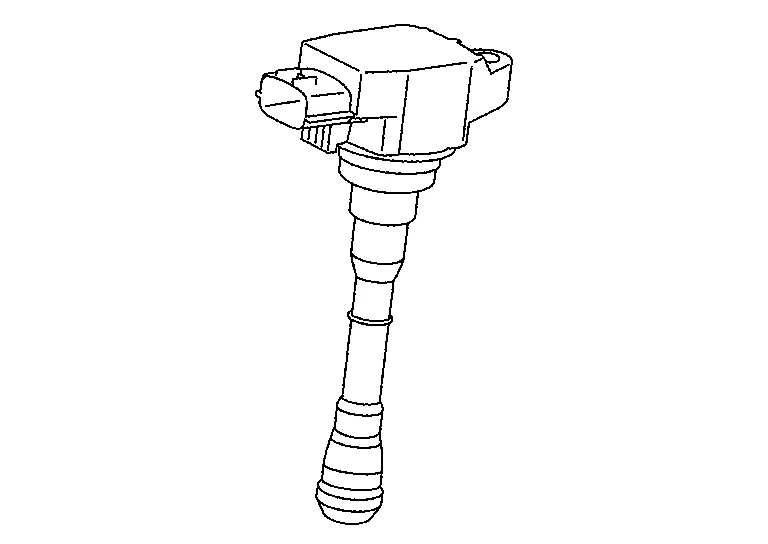
Ignition coil (with power transistor) (bank 1) | Ignition Coil (With Power Transistor) |
|
PCV valve | Positive Crankcase Ventilation (PCV) |
|
Intake valve timing intermediate lock control solenoid valve (bank 1) | Intake Valve Timing Intermediate Lock Control Solenoid Valve |
|
Intake valve timing control solenoid valve (bank 1) | Intake Valve Timing Control Solenoid Valve |
|
Exhaust valve timing control solenoid valve (bank 1) | Exhaust Valve Timing Control Solenoid Valve |
|
Engine oil pressure sensor | Engine Oil Pressure Sensor |
|
Exhaust valve timing control solenoid valve (bank 2) | Exhaust Valve Timing Control Solenoid Valve |
|
Intake valve timing control solenoid valve (bank 2) | Intake Valve Timing Control Solenoid Valve |
|
Intake valve timing intermediate lock control solenoid valve (bank 2) | Intake Valve Timing Intermediate Lock Control Solenoid Valve |
|
Crankshaft position sensor (POS) | Crankshaft Position Sensor (POS) |
|
Ignition coil (with power transistor) (bank 2) | Ignition Coil (With Power Transistor) |
|
Exhaust valve timing control position sensor (bank 2) | Exhaust Valve Timing Control Position Sensor |
|
Camshaft position sensor (PHASE) (bank 2) | Camshaft Position Sensor (PHASE) |
|
Engine coolant temperature sensor | Engine Coolant Temperature Sensor |
 |
Fuel injector (bank 1) | Fuel Injector |
 |
Knock sensor (bank 1) | Knock Sensor |
 |
Knock sensor (bank 2) | Knock Sensor |
 |
Fuel injector (bank 2) | Fuel Injector |
 |
Engine oil temperature sensor | Engine Oil Temperature Sensor |
EXHAUST
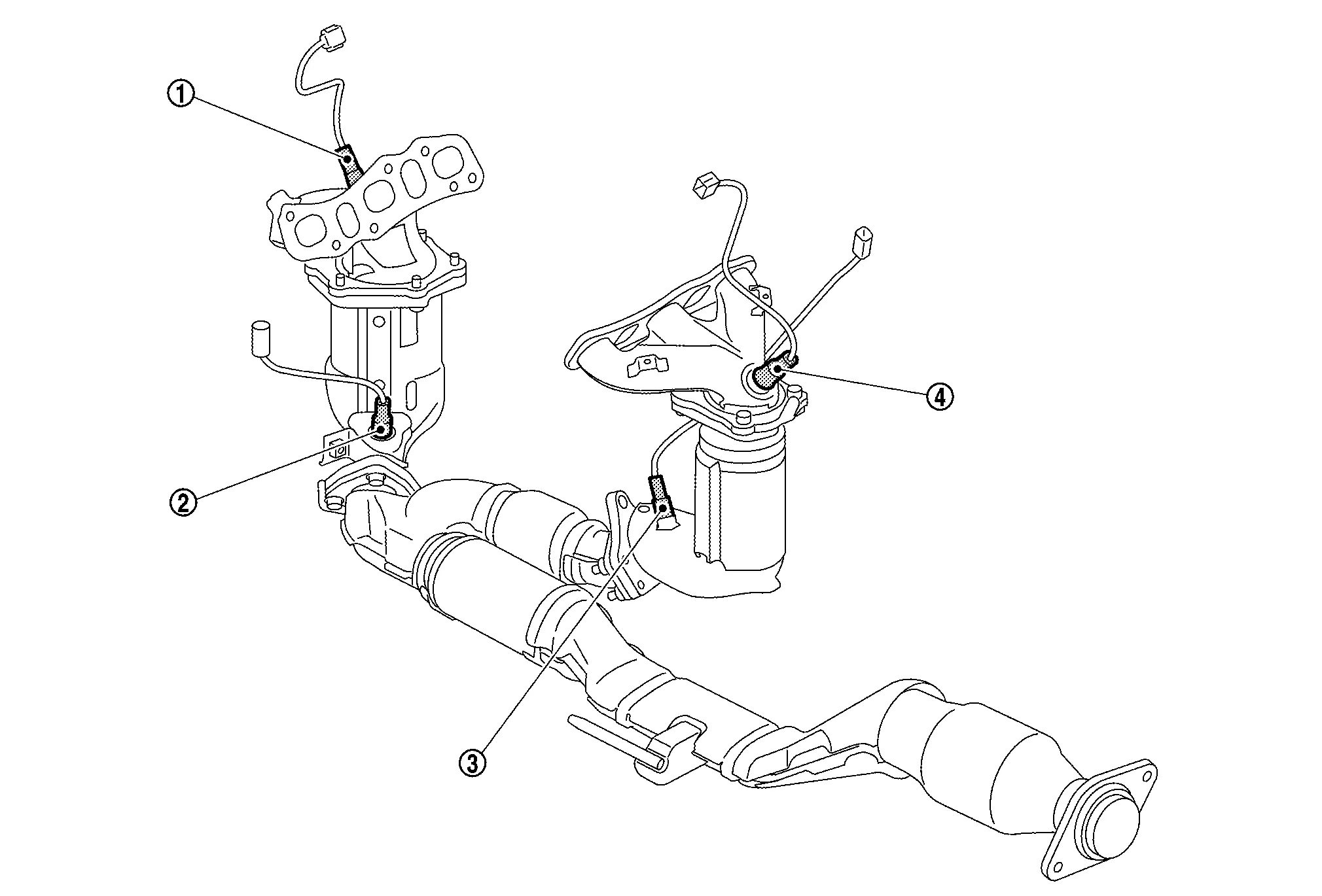
| No. | Component | Function |
|---|---|---|
|
Air fuel ratio (A/F) sensor 1 (bank 2) | Air Fuel Ratio (A/F) Sensor 1 |
|
Heated oxygen sensor 2 (bank 2) | Heated Oxygen Sensor 2 |
|
Heated oxygen sensor 2 (bank 1) | Heated Oxygen Sensor 2 |
|
Air fuel ratio (A/F) sensor 1 (bank 1) | Air Fuel Ratio (A/F) Sensor 1 |
BODY
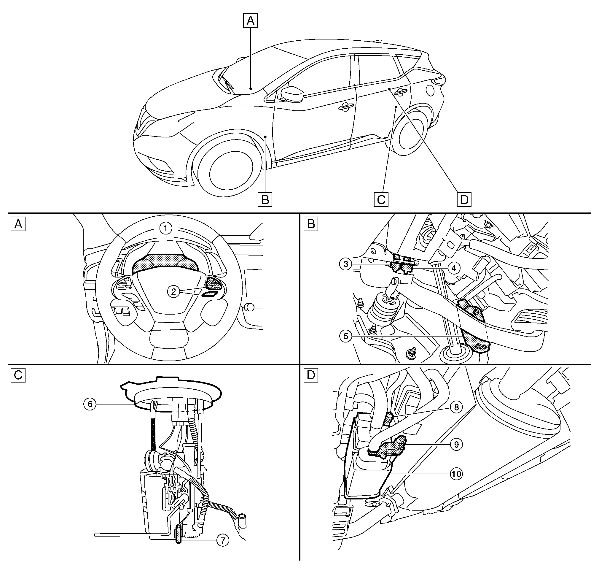
|
Instrument panel periphery (driver side) | |
Pedal periphery | |
Inside fuel tank periphery |
 |
Behind fuel tank periphery | ||||
| : Nissan Murano Vehicle front |
| No. | Component | Function | |
|---|---|---|---|
|
Combination meter | Malfunction indicator lamp (MIL) | Malfunction Indicator Lamp (MIL) |
| Information display |
The operation mode of the ASCD is indicated on the information display in the combination meter. ECM transmits the status signal to the combination meter via CAN communication according to ASCD operation. |
||
|
ASCD steering switch | ASCD Steering Switch | |
|
Stop lamp switch | Stop Lamp Switch & Brake Pedal Position Switch | |
|
Brake pedal position switch | Stop Lamp Switch & Brake Pedal Position Switch | |
|
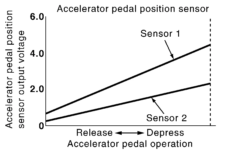
Accelerator pedal position sensor | Accelerator Pedal Position Sensor | |
|
Fuel level sensor unit and fuel pump (with fuel tank temperature sensor) |
Fuel Level Sensor Unit and Fuel Pump (With Fuel Tank Temperature Sensor) Refer to Exploded View for detailed installation location. |
|
|
Fuel tank temperature sensor | ||
|
EVAP control system pressure sensor | System” diagnosis. EVAP Control System Pressure Sensor | |
|
EVAP canister vent control valve | EVAP Canister Vent Control Valve | |
|
EVAP canister | EVAP Canister | |
The accelerator pedal position sensor is installed on the upper end of the accelerator pedal assembly. The sensor detects the accelerator position and sends a signal to the ECM.
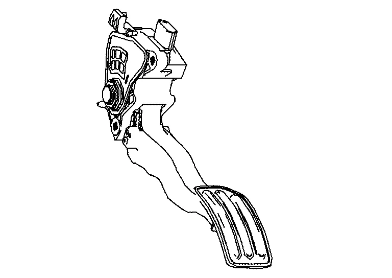
Accelerator pedal position sensor has two sensors. These sensors are a kind of potentiometers which transform the accelerator pedal position into output voltage, and emit the voltage signal to the ECM. In addition, these sensors detect the opening and closing speed of the accelerator pedal and feed the voltage signals to the ECM. The ECM judges the current opening angle of the accelerator pedal from these signals and controls the throttle control motor based on these signals.
Idle position of the accelerator pedal is determined by the ECM receiving the signal from the accelerator pedal position sensor. The ECM uses this signal for the engine operation such as fuel cut.
DESCRIPTION
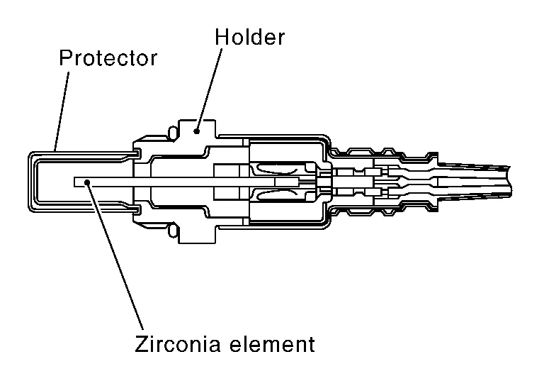
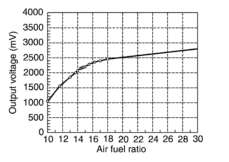
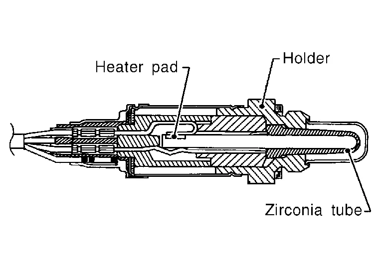
The air fuel ratio (A/F) sensor 1 is a planar one-cell limit current sensor. The sensor element of the A/F sensor 1 is composed an electrode layer, which transports ions. It has a heater in the element.
The sensor is capable of precise measurement  = 1, but also in the lean and rich range. Together with its control electronics, the sensor outputs a clear, continuous signal throughout a wide range.
The exhaust gas components diffuse through the diffusion layer at the sensor cell. An electrode layer is applied voltage, and this current relative oxygen density in lean. Also this current relative hydrocarbon density in rich.
Therefore, the A/F sensor 1 is able to indicate air fuel ratio by this electrode layer of current. In addition, a heater is integrated in the sensor to ensure the required operating temperature of approximately 800°C (1,472°F).
A/F SENSOR 1 HEATER
A/F sensor 1 heater is integrated in the sensor.
The ECM performs ON/OFF duty control of the A/F sensor 1 heater corresponding to the engine operating condition to keep the temperature of A/F sensor 1 element within the specified range.
ASCD steering switch has variant values of electrical resistance for each button. ECM reads voltage variation of switch, and determines which button is operated.
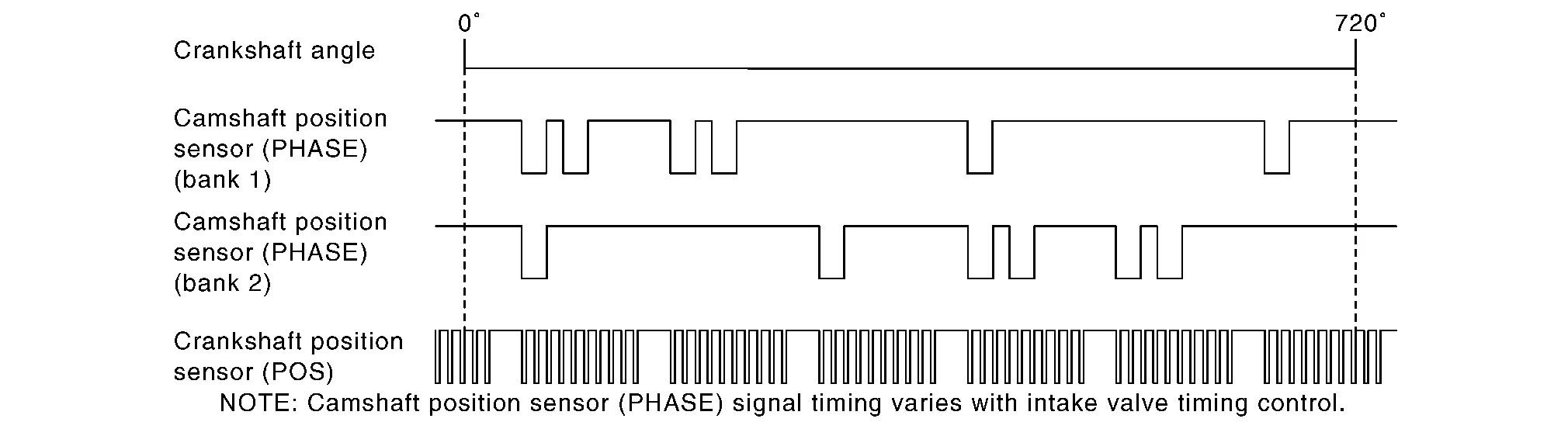
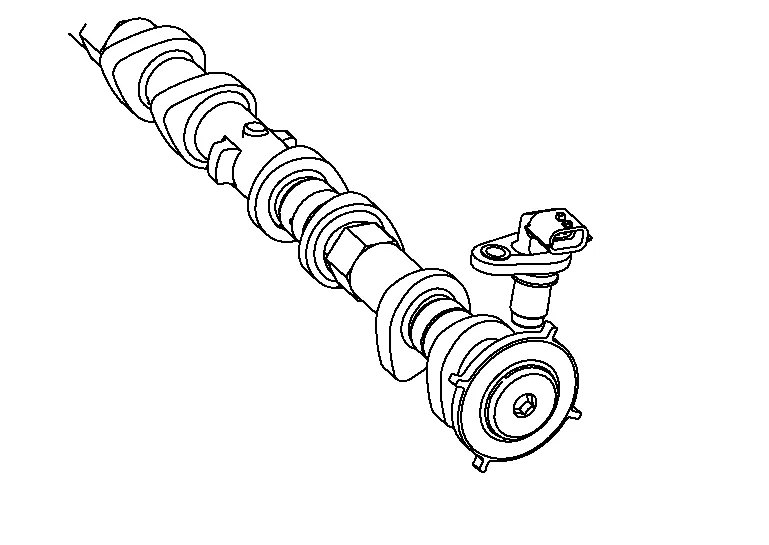
The camshaft position sensor (PHASE) senses the retraction of intake camshaft to identify a particular cylinder. The camshaft position sensor (PHASE) senses the piston position.
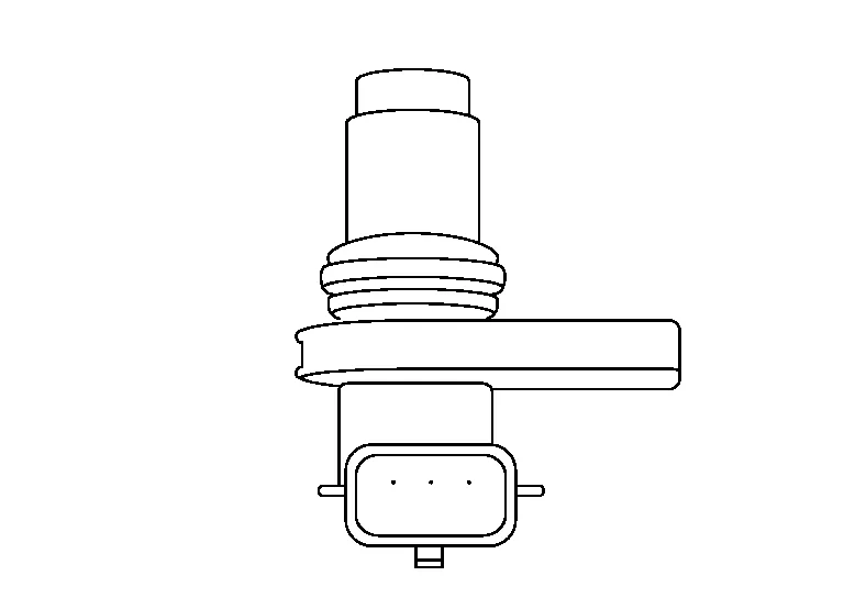
When the crankshaft position sensor (POS) system becomes inoperative, the camshaft position sensor (PHASE) provides various controls of engine parts instead, utilizing timing of cylinder identification signals.
The sensor consists of a permanent magnet and Hall IC.
When engine is running, the high and low parts of the teeth cause the gap with the sensor to change.
The changing gap causes the magnetic field near the sensor to change.
Due to the changing magnetic field, the voltage from the sensor changes.
ECM receives the signals as shown in the figure.
The ECM controls the cooling fan corresponding to the vehicle speed, engine coolant temperature, refrigerant pressure, and air conditioner ON signal. The control system has 4-step control [HIGH/MIDDLE/LOW/OFF].
Cooling fan operates at each speed when the current flows in the cooling fan motor.
Refer toSystem Description for cooling fan operation.
The crankshaft position sensor (POS) is located on the oil pan facing the gear teeth (cogs) of the signal plate. It detects the fluctuation of the engine revolution.

The sensor consists of a permanent magnet and Hall IC.
When the engine is running, the high and low parts of the teeth cause the gap with the sensor to change.
The changing gap causes the magnetic field near the sensor to change.
Due to the changing magnetic field, the voltage from the sensor changes.
The ECM receives the voltage signal and detects the fluctuation of the engine revolution.
ECM receives the signals as shown in the figure.
-
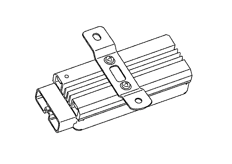
ECM (Engine Control Module) controls the engine.
-
ECM consists of a microcomputer and connectors for signal input and output and for power supply.
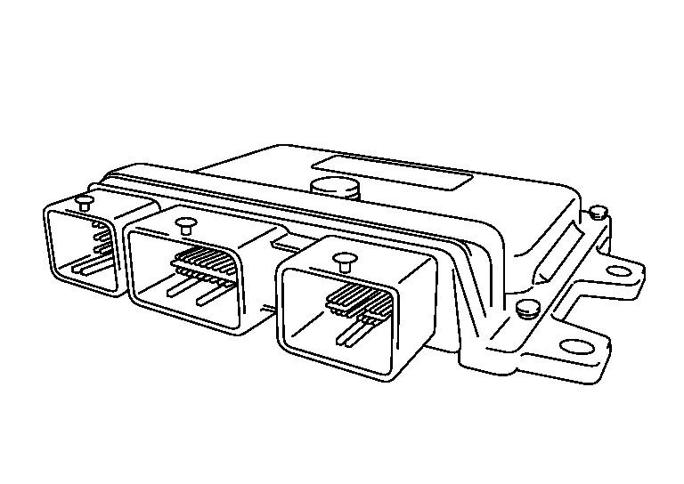
-
Battery voltage is supplied to the ECM even when the ignition switch is turned OFF for the ECM memory function of the DTC memory, the air-fuel ratio feedback compensation value memory, the idle air volume learning value memory, etc.
OUTLINE
Electric throttle control actuator consists of throttle body, throttle valve, throttle control motor and throttle position sensor.

THROTTLE CONTROL MOTOR
The throttle control motor is operated by the ECM and it opens and closes the throttle valve.
The current opening angle of the throttle valve is detected by the throttle position sensor and it provides feedback to the ECM to control the throttle control motor to make the throttle valve opening angle properly in response to driving condition.
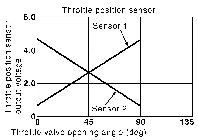
THROTTLE POSITION SENSOR
The throttle position sensor responds to the throttle valve movement.
The throttle position sensor has two sensors. These sensors are a kind of potentiometers which transform the throttle valve position into output voltage, and emit the voltage signal to the ECM. In addition, these sensors detect the opening and closing speed of the throttle valve and feed the voltage signals to the ECM. The ECM judges the current opening angle of the throttle valve from these signals and the ECM controls the throttle control motor to make the throttle valve opening angle properly in response to driving condition.
In the idle range, ECM turns OFF the electronically-controlled engine mount control solenoid valve and applies manifold pressure to the electronically-controlled engine mount. This decreases damping force of the electronically-controlled engine mount and absorbs vibrations traveling from the engine to the body for improving the quietness.
In the driving range, ECM turns ON the electronically-controlled engine mount control solenoid valve and cuts manifold pressure applied on the electronically-controlled engine mount. This increases damping force of the electronically-controlled engine mount and reduces vibrations generated during driving.
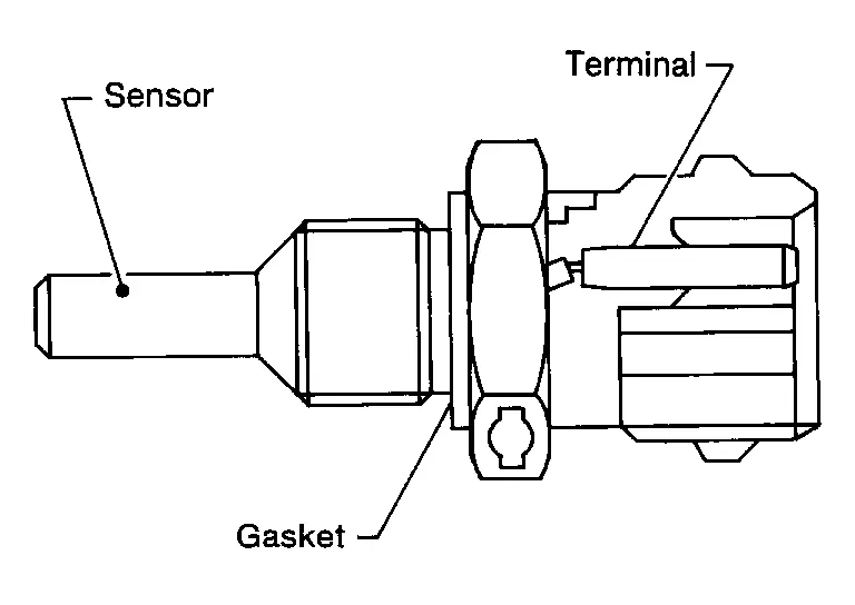
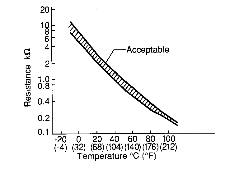
The engine coolant temperature sensor is used to detect the engine coolant temperature. The sensor modifies a voltage signal from the ECM. The modified signal returns to the ECM as the engine coolant temperature input. The sensor uses a thermistor which is sensitive to the change in temperature. The electrical resistance of the thermistor decreases as temperature increases.
<Reference data>
|
Engine coolant temperature [°C (°F)] | Voltage* (V) | Resistance (kΩ) |
|---|---|---|
| –10 (14) | 4.4 | 7.0 - 11.4 |
| 20 (68) | 3.5 | 2.37 - 2.63 |
| 50 (122) | 2.2 | 0.68 - 1.00 |
| 90 (194) | 0.9 | 0.236 - 0.260 |
*: These data are reference values and are measured between ECM terminals.
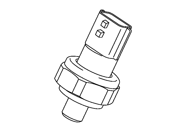
The engine oil pressure (EOP) sensor is detects engine oil pressure and transmits a voltage signal to the ECM.
The engine oil temperature sensor is used to detect the engine oil temperature. The sensor modifies a voltage signal from the ECM. The modified signal returns to the ECM as the engine oil temperature input. The sensor uses a thermistor which is sensitive to the change in temperature. The electrical resistance of the thermistor decreases as temperature increases.
<Reference data>
|
Engine oil temperature [°C (°F)] | Voltage* (V) | Resistance (kΩ) |
|---|---|---|
| –10 (14) | 4.4 | 7.0 - 11.4 |
| 20 (68) | 3.5 | 2.37 - 2.63 |
| 50 (122) | 2.2 | 0.68 - 1.00 |
| 90 (194) | 0.9 | 0.236 - 0.260 |
| 110 (230) | 0.6 | 0.143 - 0.153 |
*: These data are reference values and are measured between ECM terminals.
The fuel vapor in the sealed fuel tank is led into the EVAP canister which contains activated carbon and the vapor is stored there when the engine is not operating or when refueling to the fuel tank.
For details, refer to System Description.
The EVAP canister purge volume control solenoid valve is used to control the flow rate of fuel vapor from the EVAP canister. The EVAP canister purge volume control solenoid valve is moved by ON/OFF pulses from the ECM. The longer the ON pulse, the greater the amount of fuel vapor that will flow through the valve.
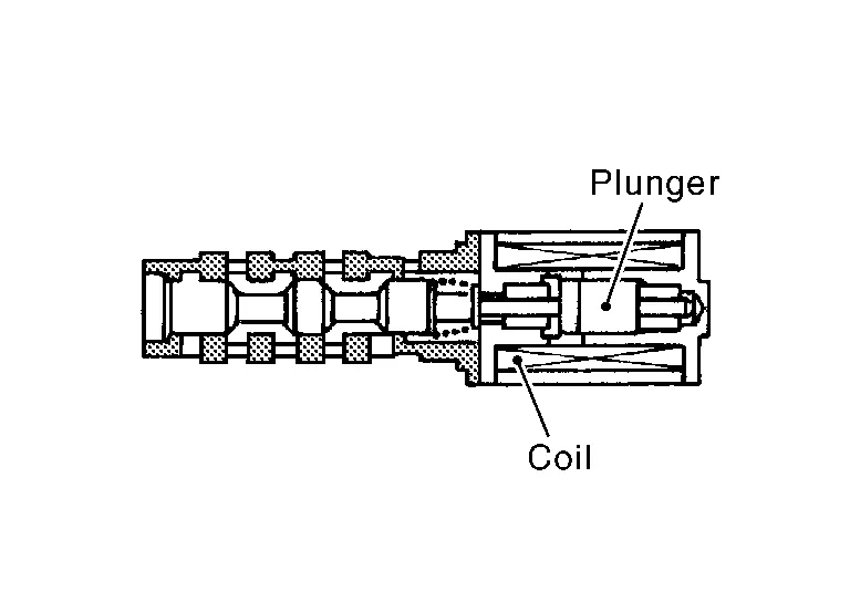
The EVAP canister vent control valve is located on the EVAP canister and is used to seal the canister vent.

This solenoid valve responds to signals from the ECM. When the ECM sends an ON signal, the coil in the solenoid valve is energized. A plunger will then move to seal the canister vent. The ability to seal the vent is necessary for the on board diagnosis of other evaporative emission control system components.
This solenoid valve is used only for diagnosis, and usually remains opened.
When the vent is closed, under normal purge conditions, the evaporative emission control system is depressurized and allows “EVAP Control System” diagnosis.
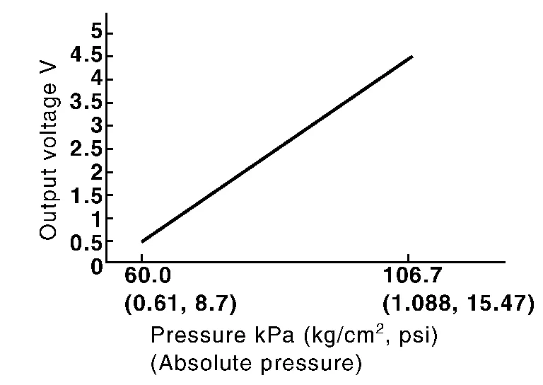
The EVAP control system pressure sensor detects pressure in the purge line. The sensor output voltage to the ECM increases as pressure increases.
The fuel injector is a small, precise solenoid valve. When the ECM supplies a ground to the fuel injector circuit, the coil in the fuel injector is energized. The energized coil pulls the ball valve back and allows fuel to flow through the fuel injector into the intake manifold. The amount of fuel injected depends upon the injection pulse duration. Pulse duration is the length of time the fuel injector remains open. The ECM controls the injection pulse duration based on engine fuel needs.
FUEL PUMP
The ECM activates the fuel pump for 1 second after the ignition switch is turned ON to improve engine start ability. If the ECM receives an engine speed signal from the camshaft position sensor (PHASE), it knows that the engine is rotating, and causes the pump to operate. If the engine speed signal is not received when the ignition switch is ON, the engine stalls. The ECM stops pump operation and prevents battery discharging, thereby improving safety. The ECM does not directly drive the fuel pump. It sends the control signal to the fuel pump control module, which in turn controls the fuel pump.
| Condition | Fuel pump operation |
|---|---|
| Ignition switch is turned to ON. | Operates for 1 second. |
| Engine running and cranking | Operates. |
| When engine is stopped | Stops in 1.5 seconds. |
| Except as shown above | Stops. |
FUEL LEVEL SENSOR
The fuel level sensor is mounted in the fuel level sensor unit.
The sensor detects a fuel level in the fuel tank and transmits a signal to the combination meter. The combination meter sends the fuel level sensor signal to the ECM via the CAN communication line.
It consists of two parts, one is mechanical float and the other is variable resistor. Fuel level sensor output voltage changes depending on the movement of the fuel mechanical float.
FUEL TANK TEMPERATURE SENSOR
The fuel tank temperature sensor is used to detect the fuel temperature inside the fuel tank. The sensor modifies a voltage signal from the ECM. The modified signal returns to the ECM as the fuel temperature input. The sensor uses a thermistor which is sensitive to the change in temperature. The electrical resistance of the thermistor decreases as temperature increases.
<Reference data>
|
Fluid temperature [°C (°F)] |
Voltage* (V) |
Resistance (kΩ) |
|---|---|---|
| 20 (68) | 3.5 | 2.3 - 2.7 |
| 50 (122) | 2.2 | 0.79 - 0.90 |
*: These data are reference values and are measured between ECM terminals 95 (Fuel tank temperature sensor) and ground.
When driving conditions demand a decrease in fuel supply, the fuel pump control module (FPCM) reduces the supply voltage to the fuel pump. When driving conditions demand an increase in fuel supply (during engine start, low engine coolant temperature or high load), the supply voltage to the fuel pump is increased.
DESCRIPTION
The heated oxygen sensor 2, after three way catalyst (manifold), monitors the oxygen level in the exhaust gas.
Even if switching characteristics of the air fuel ratio (A/F) sensor 1 are shifted, the air fuel ratio is controlled to stoichiometric, by the signal from the heated oxygen sensor 2.
This sensor is made of ceramic zirconia. The zirconia generates voltage from approximately 1 V in richer conditions to 0 V in leaner conditions.
Under normal conditions the heated oxygen sensor 2 is not used for engine control operation.
HEATED OXYGEN SENSOR 2 HEATER
Heated oxygen sensor 2 heater is integrated in the sensor.
The ECM performs ON/OFF control of the heated oxygen sensor 2 heater corresponding to the engine speed, amount of intake air and engine coolant temperature.
| Engine speed | Heated oxygen sensor 2 heater |
|---|---|
| Above 3,600 rpm | OFF |
|
Below 3,600 rpm after the following conditions are met.
|
ON |
The ignition signal from the ECM is sent to and amplified by the power transistor. The power transistor turns ON and OFF the ignition coil primary circuit. This ON/OFF operation induces the proper high voltage in the coil secondary circuit.
Intake valve timing control solenoid valve is activated by ON/OFF pulse duty (ratio) signals from the ECM.
The intake valve timing control solenoid valve changes the oil amount and direction of flow through intake valve timing control unit or stops oil flow.
The longer pulse width advances valve angle.
The shorter pulse width retards valve angle.
When ON and OFF pulse widths become equal, the solenoid valve stops oil pressure flow to fix the intake valve angle at the control position.
Intake valve timing intermediate lock control solenoid valve is activated by ON/OFF signals from the ECM.
The intake valve timing intermediate lock control solenoid valve opens/closes the path of oil pressure acting on the lock pin in the camshaft sprocket (INT).
-
When the solenoid valve becomes ON, oil pressure to the lock pin is drained to perform intermediate lock.
-
When the solenoid valve becomes OFF, oil pressure is acted on the lock pin to release the intermediate lock.
Exhaust valve timing control position sensor detects the protrusion of the signal plate installed to the exhaust camshaft front end.
This sensor signal is used for sensing a position of the exhaust camshaft.
The sensor consists of a permanent magnet and Hall IC.
When engine is running, the high and low parts of the teeth cause the gap with the sensor to change.
The changing gap causes the magnetic field near the sensor to change.
Due to the changing magnetic field, the voltage from the sensor changes.
Exhaust valve timing control solenoid valve is activated by ON/OFF pulse duty (ratio) signals from the ECM.
The exhaust valve timing control solenoid valve changes the oil amount and direction of flow through exhaust valve timing control unit or stops oil flow.
The longer pulse width retards valve angle.
The shorter pulse width advances valve angle.
When ON and OFF pulse widths become equal, the solenoid valve stops oil pressure flow to fix the exhaust valve angle at the control position.
The knock sensor is attached to the cylinder block. It senses engine knocking using a piezoelectric element. A knocking vibration from the cylinder block is sensed as vibrational pressure. This pressure is converted into a voltage signal and sent to the ECM.
Malfunction Indicator lamp (MIL) is located on the combination meter.
MIL will illuminate when the ignition switch is turned ON without the engine running. This is a bulb check.
When the engine is started, MIL should turn OFF. If the MIL remains illuminated, the on board diagnostic system has detected an engine system malfunction.
For details, refer to Malfunction Indicator Lamp .
MASS AIR FLOW SENSOR
The mass air flow sensor is placed in the stream of intake air. It measures the intake flow rate by measuring a part of the entire intake flow. The mass air flow sensor controls the temperature of the heater in sensing element to a certain amount.
The temperature distribution around the heater changes according to the increase in intake air volume. The change is detected by a thermistor and the air volume data is sent to ECM by the MAF sensor.
INTAKE AIR TEMPERATURE SENSOR
The intake air temperature sensor is built-into mass air flow sensor. The sensor detects intake air temperature and transmits a signal to the ECM.
The temperature sensing unit uses a thermistor which is sensitive to the change in temperature.
<Reference data>
|
Intake air temperature [°C (°F)] | Voltage* (V) |
|---|---|
| 25 (77) | 1.9 – 2.1 |
| 80 (176) | 3.2 – 3.4 |
*: These data are reference values on the diagnosis tool.
Oil pressure warning lamp is located on the combination meter.

It indicates the low pressure of the engine oil and the malfunction of the engine oil pressure system.
Combination meter turns the oil pressure warning lamp ON/OFF according to the oil pressure warning lamp signal received from ECM via CAN communication.
For details, refer to System Description.
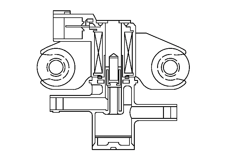
The power valves are used to control the suction passage of the variable induction air control system. They are set in the fully closed or fully opened position by the power valve actuators operated by the vacuum stored in the vacuum tank. The vacuum to power valve actuators is controlled by the VIAS control solenoid valves.
The refrigerant pressure sensor is installed at the condenser of the air conditioner system. The sensor uses an electrostatic volume pressure transducer to convert refrigerant pressure to voltage. The voltage signal is sent to ECM, and ECM controls cooling fan system.
Stop lamp switch and brake pedal position switch are installed to brake pedal bracket.
ECM detects the state of the brake pedal by those two types of input (ON/OFF signal).
| Brake pedal | Brake pedal position switch | Stop lamp switch |
|---|---|---|
| Released | ON | OFF |
| Depressed | OFF | ON |
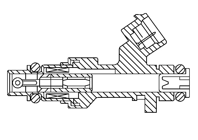
The VIAS control solenoid valve cuts the intake manifold vacuum signal for power valve control. It responds to ON/OFF signals from the ECM. When the solenoid is OFF, the vacuum signal from the intake manifold is cut. When the ECM sends an ON signal the coil pulls the plunger downward and sends the vacuum signal to the power valve actuator.

 Structure and Operation
Positive Crankcase Ventilation (PCV)
This system returns blow-by gas to the intake manifold.The positive crankcase ventilation (PCV) valve is provided to conduct crankcase blow-by gas to the intake manifold...
Other information:
Nissan Murano (Z52) 2015-2024 Service Manual: Front Coil Spring and Strut
Exploded View 1. Piston rod lock nut 2. Strut mount insulator 3. Strut mount bearing 4. Front coil spring 5. Bound bumper 6. Lower rubber seat 7. Strut Front Removal and Installation REMOVALRemove strut bolt access panel from cowl top...
Nissan Murano (Z52) 2015-2024 Service Manual: Brake Fluid Level and Leaks
Inspection BRAKE FLUID LEVEL Make sure that the brake fluid level in the reservoir sub tank is between the MAX and MIN lines. Visually check around the reservoir sub tank and reservoir tank for brake fluid leakage. If the brake fluid level is excessively low, check the brake system for leakage...
Categories
- Manuals Home
- Nissan Murano Owners Manual
- Nissan Murano Service Manual
- Settings
- Warning lights
- Vehicle Dynamic Control (VDC) OFF switch
- New on site
- Most important about car