Nissan Murano: Automatic Drive Positioner :: System Description / Component Parts. Automatic Drive Positioner System

| A. | Steering column | B. | LH side of instrument panel (view with instrument panel removed) | C. | Steering column (view with assembly removed) |
| D. | View of left front door finisher | E. | Driver seat bottom (view with seat removed) | F. | LH side of driver seat |
| No. | Component | Function | |
|---|---|---|---|
| 1. | Door mirror LH (RH similar) | Door mirror motor |
Makes mirror face operate from side to side and up and down with the electric power that automatic drive positioner control unit supplies. Refer to Component Parts Location for detailed component location. |
| Mirror sensor |
|
||
| 2. | BCM (Body Control Module) |
Recognizes the following status and transmits it to driver seat control unit via CAN communication.
|
|
| 3. | IPDM E/R (Intelligent Power Distribution Module Engine Room) |
Transmits the detention switch signal to driver seat control unit via CAN communication. Refer to Component Parts Location for detailed component location. |
|
| 4. | CAN gateway | Refer to Component Parts Location for detail component location. | |
| 5. | ABS actuator and electric unit (control unit) |
Transmits the Nissan Murano vehicle speed signal to driver seat control unit via CAN communication. Refer to Component Parts Location for detailed component location. |
|
| 6. | ECM (Engine Control Module) | Refer to ECM. | |
| 7. | TCM (Transmission Control Module) | Refer to TCM. | |
| 8. | Combination meter | Transmits the Nissan Murano vehicle speed signal to driver seat control unit via CAN communication. | |
| 9. | ADP steering switch (tilt & telescopic switch) (if equipped) | Refer to ADP Steering Switch. | |
| 10. | Automatic drive positioner control unit | Refer to Automatic Drive Positioner Control Unit. | |
| 11. | Tilt motor (if equipped) | Tilt motor | Refer to Tilt & Telescopic Motor. |
| Tilt sensor | |||
| 12. | Telescopic motor (if equipped) | Telescopic motor | |
| Telescopic sensor | |||
| 13. | Seat memory switch | Refer to Seat Memory Switch. | |
| 14. | Door mirror remote control switch | Mirror switch |
|
| Select switch |
|
||
| 15. | Reclining motor LH | Reclining motor |
|
| Reclining sensor |
|
||
| 16. | Lifting motor LH (rear) | Lifting motor (rear) |
|
| Lifting sensor (rear) |
|
||
| 17. | Sliding motor LH | Sliding motor |
|
| Sliding sensor |
|
||
| 18. | Driver seat control unit | Refer to Driver Seat Control Unit. | |
| 19. | Lifting motor LH (front) | Lifting motor (front) |
|
| Lifting sensor (front) |
|
||
|
20. |
Power seat switch LH | Sliding switch |
|
| Reclining switch |
|
||
| Lifting switch (front) |
|
||
| Lifting switch (rear) |
|
||
-
It communicates with driver seat control unit via UART communication.

-
Performs various controls with the instructions of driver seat control unit.
-
Performs the controls of tilt & telescopic and door mirror.
-
Operates steering column and door mirror with the signal from the driver seat control unit.
-
Main unit of automatic drive positioner system.
-
It is connected to the CAN communication system.
-
It communicates with automatic drive positioner control unit via UART communication.
-
The address of each part is recorded.
-
Operates each motor of seat to the registered position.
-
Requests the operation of steering column and door mirror to automatic drive positioner control unit.
-
Performs the control of seat memory switch.
-
Operates the specific seat motor with the signal from power seat switch LH.

SET SWITCH
It is used for registration and setting change of driving position.
SEAT MEMORY SWITCH
-
The maximum 2 driving positions can be registered by memory switch 1 and 2.
-
Driving position is set to the registered driving position when memory switch is pressed while operation conditions are satisfied.
SEAT MEMORY INDICATOR
Memory indicator indicates the status of automatic drive positioner system by turning ON or blinking.
-
ADP steering switch is equipped to steering column.

-
The operation signal is input to automatic drive positioner control unit when switch is operated.
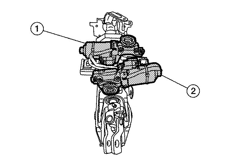
TILT MOTOR
-
Tilt motor (1) is installed to steering column assembly.
-
Tilt motor is activated with automatic drive positioner control unit.
-
Steering column is tilted upward/downward by changing the rotation direction of tilt motor.
TILT SENSOR
-
Tilt sensor is integrated in tilt motor (1).
-
The resistance of tilt sensor is changed according to the up/down position of steering column.
-
The terminal voltage of driver seat control unit will be changed according to a change of tilt sensor resistance.
-
Driver seat control unit calculates the tilt position from the voltage.
TELESCOPIC MOTOR
-
Telescopic motor (2) is installed to steering column assembly.
-
Telescopic motor is activated with automatic drive positioner control unit.
-
Compresses steering column by changing the rotation direction of telescopic motor.
TELESCOPIC SENSOR
-
Telescopic sensor is integrated in telescopic motor (2).
-
The resistance of telescopic sensor is changed according to the forward/backward position of steering column.
-
The terminal voltage of driver seat control unit will be changed according to a change of telescopic sensor resistance.
-
Driver seat control unit calculates the telescopic position from the voltage.

 System
..
Other information:
Nissan Murano (Z52) 2015-2024 Service Manual: Control Valve
Exploded View 1. Transaxle assembly 2. Terminal cord assembly 3. Control valve 4. Bracket 5. O-ring 6. Oil strainer assembly 7. Oil pan gasket 8. Oil pan 9. Drain plug 10. Drain plug gasket 11. Magnet 12...
Nissan Murano (Z52) 2015-2024 Service Manual: Ebd Function
System Description SYSTEM DIAGRAM By preventing rear wheel slip increase through rear wheel brake force (brake fluid pressure) control that is electronically controlled when slight slip on front and rear wheels is detected during braking, stability during braking is improved...
Categories
- Manuals Home
- Nissan Murano Owners Manual
- Nissan Murano Service Manual
- Vehicle Dynamic Control (VDC) OFF switch
- System malfunction
- All-Wheel Drive (AWD) (if so equipped)
- New on site
- Most important about car
Luggage hooks

When securing items using luggage hooks located on the back of the seat or side finisher do not apply a load over more than 6.5 lbs. (29 N) to a single hook.
The luggage hooks that are located on the floor should have loads less than 110 lbs. (490 N) to a single hook.