
Nissan Murano: Side Radar (rear Left) (side Radar Lh) / C1b50-49 Side Radar Malfunction
DTC DETECTION LOGIC
| DTC No. |
CONSULT screen terms (Trouble diagnosis content) | DTC detection condition | |
|---|---|---|---|
| C1B50-49 |
SIDE RDR MALFUNCTION (Side radar malfunction) |
Diagnosis condition | When ignition switch is ON. |
| Signal (terminal) | – | ||
| Threshold | Side radar malfunction | ||
| Diagnosis delay time | – | ||
POSSIBLE CAUSE
Side radar LH
FAIL-SAFE
The following systems are canceled:
-
Blind Spot Warning (BSW)
-
Rear Cross Traffic Alert (RCTA)
PERFORM DTC CONFIRMATION PROCEDURE
 CONSULT
-
Start the engine.
-
Select “All DTC Reading” mode.
-
Check if “C1B50-49” is detected as the current malfunction in “Self Diagnostic Result” mode of “Side radar (Rear left)”.
Is the “C1B50-49” detected as the current malfunction?
YES>>Refer to Diagnosis Procedure.
NO>>To check malfunction symptom before repair: Refer to Intermittent Incident.
NO>>Confirmation after repair: Inspection End.
PERFORM SELF DIAGNOSTIC RESULT
CONSULT
-
Turn ignition switch ON.
-
Select “Self Diagnostic Result” mode of “Side radar (Rear left)”.
-
Select “ERASE”.
-
Turn ignition switch OFF.
-
Turn ignition switch ON.
-
Check if any DTC other than “C1B50-49” is detected in “Self Diagnostic Result” mode of “Side radar (Rear left)”.
Is any DTC detected?
YES>>Perform diagnosis on the detected DTC and repair or replace the malfunctioning part. Refer to DTC Index.
NO>>Replace the side radar LH. Refer to Removal and Installation.

 C1b51-16 Blind Spot Warning Indicator Short Circuit
DTC Description
DTC DETECTION LOGIC DTC No.
CONSULT screen terms
(Trouble diagnosis content) DTC detection condition
C1B51-16
BSW/BSI IND SHORT CIR
(Blind Spot Warning indicator short circuit)
Diagnosis condition
When ignition switch is ON...
Other information:
Nissan Murano (Z52) 2015-2024 Owners Manual: Readiness for Inspection/Maintenance (I/M) test
WARNING A vehicle equipped with All -Wheel Drive (AWD) should never be tested using a two wheel dynamometer (such as the dynamometers used bysomestates for emissions testing), or similar equipment. Make sure you inform the test facility personnel that your vehicle is equipped with AWD before it is placed on a dynamometer...
Nissan Murano (Z52) 2015-2024 Owners Manual: Answer back horn feature
If desired, the answer back horn feature can be deactivated using the Intelligent Key. When it is deactivated and the button is pushed, the hazard indicator lights flash twice. When the button is pushed, neither the hazard indicator lights nor the horn operates...
Categories
- Manuals Home
- Nissan Murano Owners Manual
- Nissan Murano Service Manual
- High Beam Assist (if so equipped)
- Passenger compartment
- GAS STATION INFORMATION
- New on site
- Most important about car
LATCH (Lower Anchors and Tethers for CHildren) system
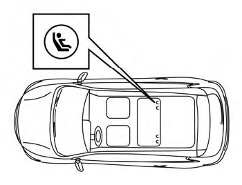
LATCH system lower anchor locations - bench seat
Your vehicle is equipped with special anchor points that are used with LATCH system compatible child restraints. This system may also be referred to as the ISOFIX or ISOFIX compatible system. With this system, you do not have to use a vehicle seat belt to secure the child restraint unless the combined weight of the child and child restraint exceeds 65 lbs. (29.5 kg). If the combined weight of the child and child restraint is greater than 65 lbs. (29.5 kg), use the vehicle’s seat belt (not the lower anchors) to install the child restraint. Be sure to follow the child restraint manufacturer’s instructions for installation.
