
Nissan Murano: Suspension / Road Wheels & Tires :: Preparation. Preparation
Nissan Murano (Z52) 2015-2024 Service Manual / Suspension / Road Wheels & Tires :: Preparation. Preparation
|
Tool number (TechMate No.) Tool name | Description | |
|---|---|---|
|
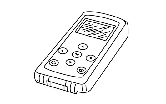
— (J-50190) Signal Tech II |
|
|
|
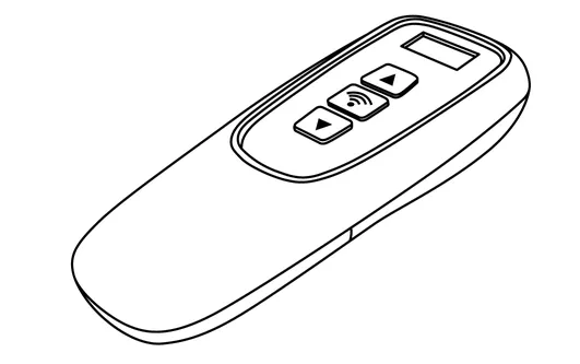
KV48105501 (J-45295-A) Transmitter activation tool |
|
|
|
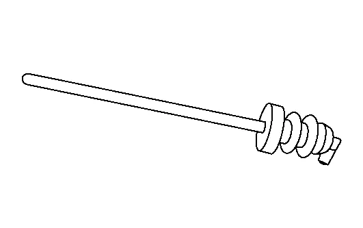
— (J-51980) TPMS Service Tool |
|
Remove and install TPMS transmitter valve stem |
| Tool name | Description | |
| Power tool |
|
Loosening nuts, screws and bolts |

 Road Wheels & Tires :: Precaution. Precautions
Precaution for Supplemental Restraint System (SRS) "AIR BAG" and "SEAT BELT PRE-TENSIONER"
The Supplemental Restraint System such as “AIR BAG” and “SEAT BELT PRE-TENSIONER”, used along with a front seat belt, helps to reduce the risk or severity of injury to the driver and front passenger for certain types of collisions...

Other information:
Nissan Murano (Z52) 2015-2024 Service Manual: Front Fog Lamp Circuit
Component Function Check CHECK FRONT FOG LAMP OPERATION CONSULT Select “EXTERNAL LAMPS” in “Active Test” mode of “IPDM E/R”. While operating the test items, check that the front fog lamp is turned ON. Fog : Front fog lamp ON Off : Front fog lamp OFF Is the inspection result normal? YES>> Front fog lamp circuit is normal...
Nissan Murano (Z52) 2015-2024 Service Manual: Meter Control Switch Signal Circuit
Diagnosis Procedure CHECK METER CONTROL SWITCH SIGNAL Ignition switch ON. Check voltage between the following terminals of the meter control switch harness connector. Meter control switch Condition Voltage (Approx.) Connector Terminals (+) (−) M27 7 4 When illumination control switch (−) is pressed 0 V Other than the above 5 V 5 When trip reset switch is pressed 0 V Other than the above 5 V 6 When illumination control switch (+) is pressed 0 V Other than the above 5 V Is the inspection result normal? YES>> Inspection End...
Categories
- Manuals Home
- Nissan Murano Owners Manual
- Nissan Murano Service Manual
- Shift lock release
- Rear bench seat adjustment
- Settings
- New on site
- Most important about car

Copyright © 2026 www.nimurano.com