Nissan Murano: Rear Suspension :: Removal and Installation / Rear Lower Link Coil Spring
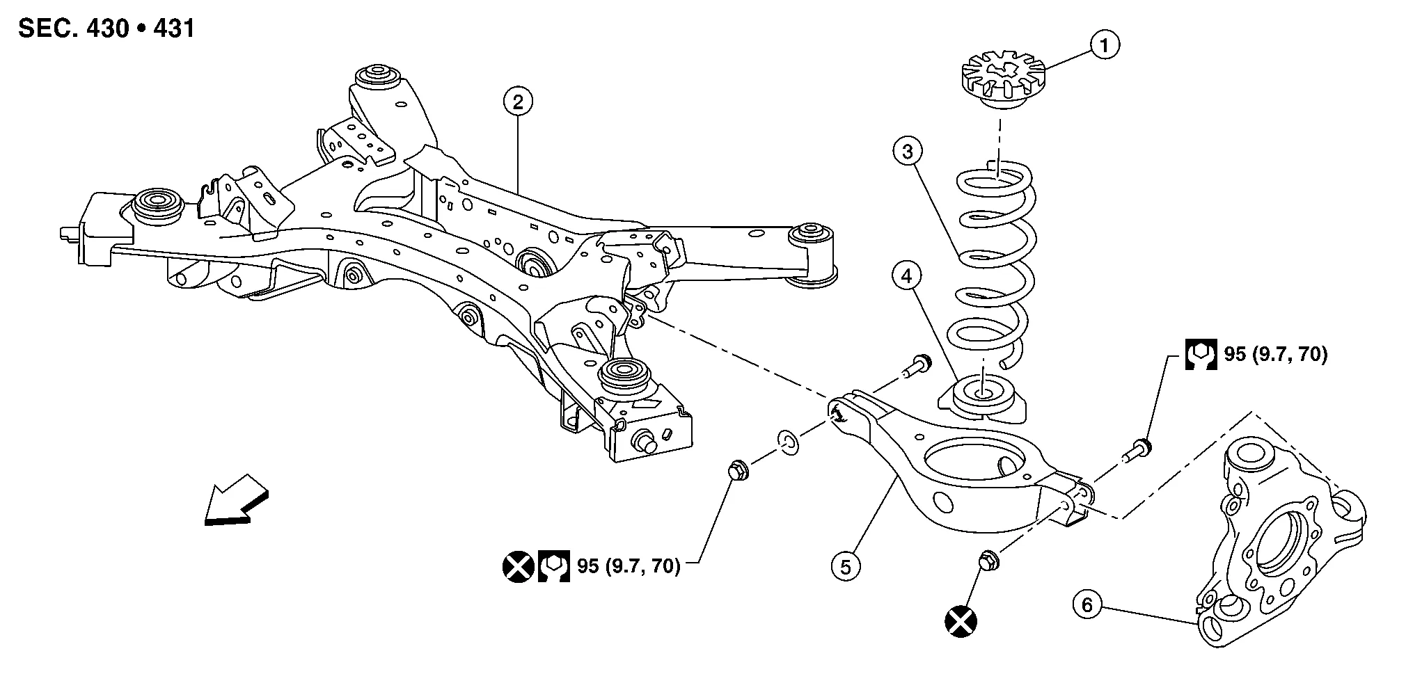
| 1. | Upper seat | 2. | Rear suspension member | 3. | Coil spring |
| 4. | Lower rubber seat | 5. | Rear lower link | 6. | Rear knuckle |
| Front |
REMOVAL
Remove the front undercover. Refer to Removal and Installation.
Support the front of vehicle with a suitable jack.
WARNING:
Place a suitable jack under the center of the front suspension member.
CAUTION:
Do not damage the front suspension member with the suitable jack.
Remove the rear wheel and tire using power tool. Refer to Removal and Installation.
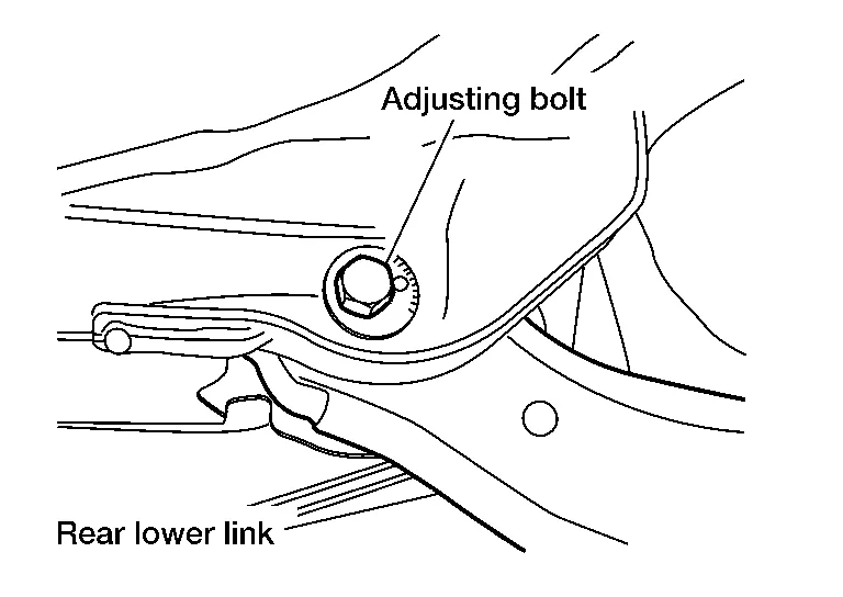
Put alignment marks on the adjusting bolt and on the rear lower link.
CAUTION:
Use paint or an equivalent for alignment marks. Do not scratch the surface.
Loosen the rear lower link adjusting bolt on the rear suspension member.
Support the rear lower link with a suitable jack.
WARNING:
Place a suitable jack under the outer end of the rear lower link.
CAUTION:
Do not damage the rear lower link with the suitable jack.
Support the rear knuckle with a suitable jack.
WARNING:
Place a suitable jack under the center of the rear knuckle.
CAUTION:
Do not damage the rear knuckle with the suitable jack.
Remove the rear lower link nut and bolt from the rear knuckle using power tool.
Slowly lower the suitable jack supporting the rear lower link. Remove the upper seat, the coil spring, and the lower rubber seat from the rear lower link.
Remove the rear lower link nut and bolt from the rear suspension member using power tool.
Remove the rear lower link.
INSTALLATION
Installation is in the reverse order of removal.
CAUTION:
Do not reuse lower link nuts.
-
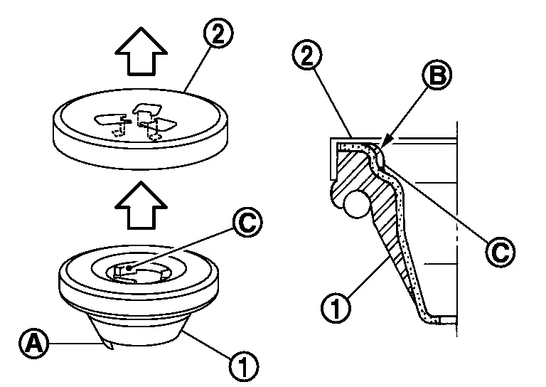
Make sure that the upper seat is attached as shown.
CAUTION:
-
Keep the upper seat (1) in place during coil spring installation. The protrusion (A) on the upper seat faces the outside of the Nissan Murano vehicle.
-
Align the tabs (C) to the upper seat openings and securely fit the bracket (2) to the tabs (B).

: Body -
-
Perform the final tightening of the parts under unladen conditions with the tires on level ground.
-
Check the wheel alignment. Refer to Inspection.
-
Adjust the neutral position of the steering angle sensor. Refer to Description.

 Rear Shock Absorber
Exploded View
1.
Rear shock absorber
2.
Piston rod lock nut
3.
Shock absorber insulator
4.
Bound bumper
Front
Removal and Installation
REMOVALRemove the rear wheel and tire using power tool...
Other information:
Nissan Murano (Z52) 2015-2024 Service Manual: Around View Monitor Control Unit
Exploded View 1. Instrument panel assembly 2. Around view monitor control unit Removal and Installation REMOVALNOTE: Before replacing around view monitor control unit, perform “Before Replace ECU” of “Read / Write Configuration” to save or print current Nissan Murano vehicle specification...
Nissan Murano (Z52) 2015-2024 Service Manual: P0196 Eot Sensor
DTC Description DTC DETECTION LOGIC Rationally incorrect voltage from the sensor is sent to ECM, compared with the voltage signals from EOT sensor and intake air temperature sensor. The comparison result of signals transmitted to ECM from each temperature sensor (IAT sensor, ECT sensor, FTT sensor, and EOT sensor) shows that the signal voltage of the EOT sensor is higher/lower than that of other temperature sensors when the engine is started with its cold state...
Categories
- Manuals Home
- Nissan Murano Owners Manual
- Nissan Murano Service Manual
- Jacking up vehicle and removing the damaged tire
- All-Wheel Drive (AWD) (if so equipped)
- Settings
- New on site
- Most important about car
Fuel gauge

The gauge indicates the approximate fuel level in the tank.
The gauge may move slightly during braking, turning, acceleration, or going up or down hills.
The gauge needle returns to 0 (Empty) after the ignition switch is placed in the OFF position.