Nissan Murano: Dtc/circuit Diagnosis / P052a Intake Valve Timing Control
DTC DETECTION LOGIC
There is a gap between the target phase angle and the detected phase angle when the engine is operating in cold conditions.
| DTC |
CONSULT screen terms (Trouble diagnosis content) |
DTC detection condition | |
| P052A |
CAMSHAFT POSITION TIMING B1 (Cold start “A” camshaft position timing over-advanced bank 1) |
Diagnosis condition | — |
| Signal (terminal) | — | ||
| Threshold | There is a gap between the target phase angle and the detected phase angle when the engine is operating in cold conditions | ||
| Diagnosis delay time | — | ||
| P052B |
CAMSHAFT POSITION TIMING B1 (Cold start “A” camshaft position timing over-retarded bank 1) |
Diagnosis condition | — |
| Signal (terminal) | — | ||
| Threshold | There is a gap between the target phase angle and the detected phase angle when the engine is operating in cold conditions | ||
| Diagnosis delay time | — | ||
| P052C |
CAMSHAFT POSITION TIMING B2 (Cold start “A” camshaft position timing over-advanced bank 2) |
Diagnosis condition | — |
| Signal (terminal) | — | ||
| Threshold | There is a gap between the target phase angle and the detected phase angle when the engine is operating in cold conditions | ||
| Diagnosis delay time | — | ||
| P052D |
CAMSHAFT POSITION TIMING B2 (Cold start “A” camshaft position timing over-retarded bank 2) |
Diagnosis condition | — |
| Signal (terminal) | — | ||
| Threshold | There is a gap between the target phase angle and the detected phase angle when the engine is operating in cold conditions | ||
| Diagnosis delay time | — | ||
POSSIBLE CAUSE
DTC P052A
-
Crankshaft position sensor
-
Camshaft position sensor
-
Intake valve timing control solenoid valve
-
Intake valve timing intermediate lock control solenoid valve
-
Accumulation of debris to the signal pick-up portion of the camshaft
-
Timing chain installation
-
Foreign matter caught in the intake valve timing control (or intermediate lock control) solenoid valve
DTC P052B
-
Crankshaft position sensor
-
Camshaft position sensor
-
Intake valve timing control solenoid valve
-
Intake valve timing intermediate lock control solenoid valve
-
Accumulation of debris to the signal pick-up portion of the camshaft
-
Timing chain installation
-
Foreign matter caught in the intake valve timing control (or intermediate lock control) solenoid valve
DTC P052C
-
Crankshaft position sensor
-
Camshaft position sensor
-
Intake valve timing control solenoid valve
-
Intake valve timing intermediate lock control solenoid valve
-
Accumulation of debris to the signal pick-up portion of the camshaft
-
Timing chain installation
-
Foreign matter caught in the intake valve timing control (or intermediate lock control) solenoid valve
DTC P052D
-
Crankshaft position sensor
-
Camshaft position sensor
-
Intake valve timing control solenoid valve
-
Intake valve timing intermediate lock control solenoid valve
-
Accumulation of debris to the signal pick-up portion of the camshaft
-
Timing chain installation
-
Foreign matter caught in the intake valve timing control (or intermediate lock control) solenoid valve
FAIL-SAFE
| Engine operating condition in fail-safe mode | ||
|---|---|---|
| Fail safe mode | Nissan Murano Vehicle behavior | |
| Intake valve timing intermediate lock control | — | |
CHECK DTC PRIORITY
If DTC P052A, P052B, P052C and P052D is displayed with DTC P0075 or P0081, first perform the confirmation procedure for DTC UXXXX or P0607.
Is applicable DTC detected?
YES>>Perform diagnosis of applicable.
-
DTC P0075: Refer to DTC Description.
-
DTC P0081: Refer to DTC Description.
GO TO 2.
PRECONDITIONING
TESTING CONDITION:
Before performing the following procedure, confirm that battery voltage is 10 V or more at idle.
 With CONSULT
-
Turn ignition switch OFF and wait at least 10 seconds.
-
Turn ignition switch ON.
-
Turn ignition switch OFF and wait at least 10 seconds.
-
Turn ignition switch ON.
-
On the CONSULT screen, select “ENGINE” >> “DATA MONITOR” >> “COOLAN TEMP/S”.
-
Check “COOLAN TEMP/S” indication value.
 With GST
Follow the procedure “With CONSULT” above.
Is the value of “COOLAN TEMP/S”−5°C (23°F) and 45°C (113°F)?
YES>>GO TO 3.
NO>>Warm up the engine until the value of “COOLAN TEMP/S” indicates −5°C (23°F) and 45°C (113°F). And then GO TO 3.
NO>>Cool the engine down to the value of “COOLAN TEMP/S” indicates −5°C (23°F) and 45°C (113°F). And then GO TO 3.
PERFORM DTC CONFIRMATION PROCEDURE-I
-
Turn ignition switch OFF and wait at 10 seconds.
-
Turn ignition switch ON.
-
Set the selector lever in N range.
-
Start the engine and let it idle for 20 seconds or more.
-
Check 1st trip DTC.
Is 1st trip DTC detected?
YES>>Proceed to Diagnosis Procedure
NO>>To check malfunction symptom before repair: Refer to Intermittent Incident.
NO>>Confirmation after repair: INSPECTION END
CHECK DTC PRIORITY
If DTC P052A, P052B, P052C and P052D is displayed with DTC P0075 or P0081, first perform the confirmation procedure for DTC UXXXX or P0607.
Is applicable DTC detected?
YES>>Perform diagnosis of applicable.
-
DTC P0075: Refer to DTC Description.
-
DTC P0081: Refer to DTC Description.
GO TO 2.
INSPECTION START
With CONSULT>>
GO TO 3.
Without CONSULT>>GO TO 4.
CHECK VTC POSITION
With CONSULT
-
Turn ignition switch ON.
-
On the CONSULT screen, select “ENGINE” >> “DATA MONITOR” >> “COOLAN TEMP/S”.
-
Check that the “COOLAN TEMP/S” indication value is between −5°C (23°F) and 45°C (113°F).
-
Start engine and wait at least 5 seconds.
-
On the CONSULT screen, select “ENGINE” >> “DATA MONITOR” >> “INT/V TIM (B1)”.
-
Check that the data monitor item indicates as follows:
Item Value (°CA) INT/V TIM (B1) 10 ± 2 INT/V TIM (B2) 10 ± 2
Is the inspection result normal?
YES>>INSPECTION END
NO>>GO TO 5.
CHECK OIL PRESSURE WARNING LAMP
-
Start engine.
-
Check that oil pressure warning lamp is not illuminated.

Is oil pressure warning lamp illuminated?
YES>>Refer to Inspection.
NO>>GO TO 6.
CHECK INTAKE VALVE TIMING INTERMEDIATE LOCK CONTROL SOLENOID VALVE
Perform Component Inspection of the intake valve timing intermediate lock control solenoid valve. Refer to Component Inspection (Intake Valve Timing Intermediate Lock Control Solenoid Valve).
Is the inspection result normal?
YES>>GO TO 6.
NO>>Repair or replace error-detected parts.
CHECK INTAKE VALVE TIMING CONTROL SOLENOID VALVE
Perform Component Inspection of the intake valve timing control solenoid valve. Refer to Component Inspection (Intake Valve Timing Control Solenoid Valve).
Is the inspection result normal?
YES>>GO TO 7.
NO>>Repair or replace error-detected parts.
CHECK CRANKSHAFT POSITION SENSOR
Perform Component Inspection of the crankshaft position sensor. Refer to Component Inspection (Crankshaft Position sensor).
Is the inspection result normal?
YES>>GO TO 8.
NO>>Repair or replace error-detected parts.
CHECK CAMSHAFT POSITION SENSOR
Perform Component Inspection of the camshaft position sensor. Refer to Component Inspection (Crankshaft Position sensor).
Is the inspection result normal?
YES>>GO TO 9.
NO>>Repair or replace error-detected parts.
CHECK CAMSHAFT (INTAKE)
Check the following.
-
Accumulation of debris on the signal plate of camshaft front end
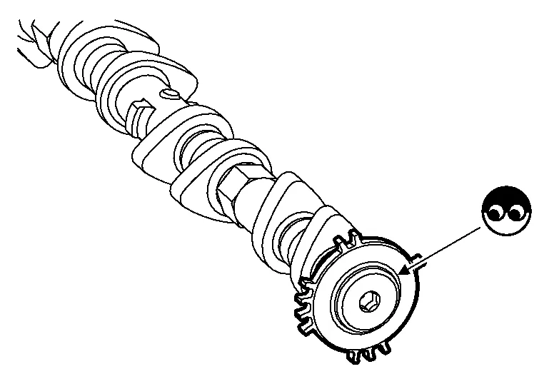
-
Chipping signal plate of camshaft front end
Is the inspection result normal?
YES>>GO TO 10.
NO>>Remove debris and clean the signal plate of camshaft front end or replace camshaft. Refer to Removal and Installation.
CHECK TIMING CHAIN INSTALLATION
Check service records for any recent repairs that may cause timing chain misalignment.
Are there any service records that may cause timing chain misalignment?
YES>>Check timing chain installation. Refer to Removal and Installation.
NO>>GO TO 11.
CHECK LUBRICATION CIRCUIT
Perform “Inspection of Camshaft Sprocket (INT) Oil Groove”. Refer to Inspection after Installation.
Is the inspection result normal?
YES>>INSPECTION END
NO>>Clean lubrication line.
CHECK INTAKE VALVE TIMING CONTROL SOLENOID VALVE-I
-
Turn ignition switch OFF.
-
Disconnect intake valve timing control solenoid valve harness connector.
-
Check resistance between intake valve timing control solenoid valve terminals as per the following.
Intake valve timing control solenoid valve Condition
Resistance + − Terminal 1 2 Temperature 20°C (68°F) 7.0 – 7.8 Ω 1 Ground ∞
(Continuity should not exist)2
Is the inspection result normal?
YES>>GO TO 2.
NO>>Replace malfunctioning intake valve timing control solenoid valve. Refer to Exploded View.
CHECK INTAKE VALVE TIMING CONTROL SOLENOID VALVE-II
-
Remove intake valve timing control solenoid valve. Refer to Exploded View.
-
Provide 12 V DC between intake valve timing control solenoid valve terminals 1 and 2, and then interrupt it. Check that the plunger moves as shown in the figure.
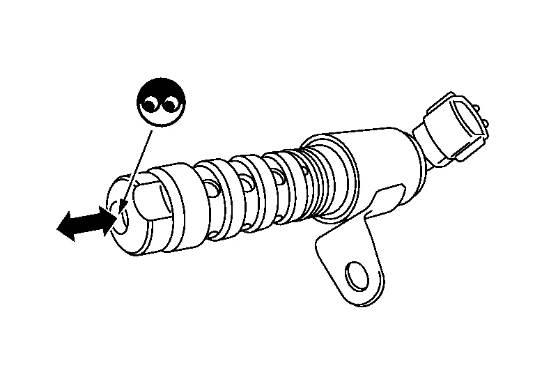
CAUTION:
Never apply 12 V DC continuously for 5 seconds or more. Doing so may result in damage to the coil in intake valve timing control solenoid valve.
 NOTE:
NOTE:
Always replace O-ring when intake valve timing control solenoid valve is removed.
Is the inspection result normal?
YES>>INSPECTION END
NO>>Replace malfunctioning intake valve timing control solenoid valve. Refer to Exploded View.
CHECK INTAKE VALVE TIMING INTERMEDIATE LOCK CONTROL SOLENOID VALVE-I
-
Turn ignition switch OFF.
-
Disconnect intake valve timing intermediate lock control solenoid valve harness connector.
-
Check resistance between intake valve timing intermediate lock control solenoid valve terminals as per the following.
Intake valve timing intermediate lock control solenoid valve Condition
Resistance + − Terminal 1 2 Temperature 20°C (68°F) 7.0 – 7.8 Ω 1 Ground ∞
(Continuity should not exist)2
Is the inspection result normal?
YES>>GO TO 2.
NO>>Replace malfunctioning intake valve timing intermediate lock control solenoid valve. Refer to Exploded View.
CHECK INTAKE VALVE TIMING INTERMEDIATE LOCK CONTROL SOLENOID VALVE-II
-
Remove intake valve timing intermediate lock control solenoid valve. Refer to Exploded View.
-
Provide 12 V DC between intake valve timing intermediate lock control solenoid valve terminals 1 and 2, and then interrupt it. Check that the plunger moves as shown in the figure.
CAUTION:
Never apply 12 V DC continuously for 5 seconds or more. Doing so may result in damage to the coil in intake valve timing intermediate lock control solenoid valve.
NOTE:
Always replace O-ring when intake valve timing intermediate lock control solenoid valve is removed.
Is the inspection result normal?
YES>>INSPECTION END
NO>>Replace malfunctioning intake valve timing intermediate lock control solenoid valve. Refer to Exploded View.
CHECK CRANKSHAFT POSITION SENSOR (POS)-1
-
Turn ignition switch OFF.
-
Loosen the fixing bolt of the sensor.
-
Disconnect crankshaft position sensor (POS) harness connector.
-
Remove the sensor.
-
Visually check the sensor for chipping.

Is the inspection result normal?
YES>>GO TO 2.
NO>>Replace crankshaft position sensor (POS). Refer to Exploded View.
CHECK CRANKSHAFT POSITION SENSOR (POS)-2
Check the resistance between crankshaft position sensor (POS) terminals as per the following.
| Crankshaft position sensor (POS) | Resistance [at 25°C (77°F)] | |
|---|---|---|
| + | − | |
| Terminal (Polarity) | ||
| 1 | 2 |
Except 0 or ∞Ω |
| 3 | ||
| 2 | 3 | |
Is the inspection result normal?
YES>>INSPECTION END
NO>>Replace crankshaft position sensor (POS). Refer to Exploded View.
CHECK CAMSHAFT POSITION SENSOR (PHASE)-1
-
Turn ignition switch OFF.
-
Loosen the fixing bolt of the sensor.
-
Disconnect camshaft position sensor (PHASE) harness connector.
-
Remove the sensor. Refer to Exploded View.
-
Visually check the sensor for chipping.

Is the inspection result normal?
YES>>GO TO 2.
NO>>Replace camshaft position sensor (PHASE).
CHECK CAMSHAFT POSITION SENSOR (PHASE)-2
Check the resistance camshaft position sensor (PHASE) terminals as per the following.
| Camshaft position sensor (PHASE) | Resistance [ Ω at 25°C (77°F)] | |
|---|---|---|
| + | − | |
| Terminals (Polarity) | ||
| 1 | 2 | Except 0 or ∞ |
| 3 | ||
| 2 | 3 | |
Is the inspection result normal?
YES>>INSPECTION END
NO>>Replace camshaft position sensor (PHASE). Refer to Exploded View.
 P0524 Engine Oil Pressure
DTC Description
DTC DETECTION LOGICAn EOP sensor signal voltage applied to ECM remains lower than the specified value continuously for 10 seconds or more when the engine speed is 1,000 rpm or more...
 P0531 Refrigerant Pressure Sensor
DTC Description
DTC DETECTION LOGIC DTC No.
CONSULT screen terms
(Trouble diagnosis content) DTC detecting condition
P0531
REFRIGERANT PRESS SENSOR A
(A/C refrigerant pressure sensor A circuit range/performance)
Diagnosis condition
Ignition switch ON
Engine running
Signal (terminal)
Refrigerant pressure sensor signal
Threshold
ECM detects that input signal is out of the specified range...
Other information:
Nissan Murano (Z52) 2015-2024 Service Manual: Front Floor Duct Nozzle
Removal and Installation REMOVALRemove the floor trim. Refer to Removal and Installation. Remove the screw and the front floor duct nozzle.INSTALLATIONInstallation is in the reverse order of removal. Exploded View 1. Instrument panel 2. Side defroster grille (LH) 3...
Nissan Murano (Z52) 2015-2024 Owners Manual: Brake precautions
Vacuum assisted brakes The brake booster aids braking by using engine vacuum. If the engine stops, you can stop the vehicle by depressing the brake pedal. However, greater foot pressure on the brake pedal will be required to stop the vehicle and stopping distance will be longer...
Categories
- Manuals Home
- Nissan Murano Owners Manual
- Nissan Murano Service Manual
- System malfunction
- Rear bench seat adjustment
- Tire rotation
- New on site
- Most important about car
Driver and passenger supplemental knee air bag

Driver’s side
The knee air bag is located in the knee bolster, on the driver’s and passenger’s side. All of the information, cautions and warnings in this manual apply and must be followed. The knee air bag is designed to inflate in higher severity frontal collisions, although it may inflate if the forces in another type of collision are similar to those of a higher severity frontal impact. It may not inflate in certain collisions.

Passenger’s side