Nissan Murano: Engine Lubrication System :: Removal and Installation / Oil Pump
REMOVAL
Remove the engine from the vehicle. Refer to Removal and Installation (FWD) or Removal and Installation (AWD).
Remove the upper oil pan. Refer to Removal and Installation (Upper Oil Pan).
Remove the timing chain. Refer to Removal and Installation.
Remove oil pump assembly.
INSTALLATION
Installation is in the reverse order of removal.
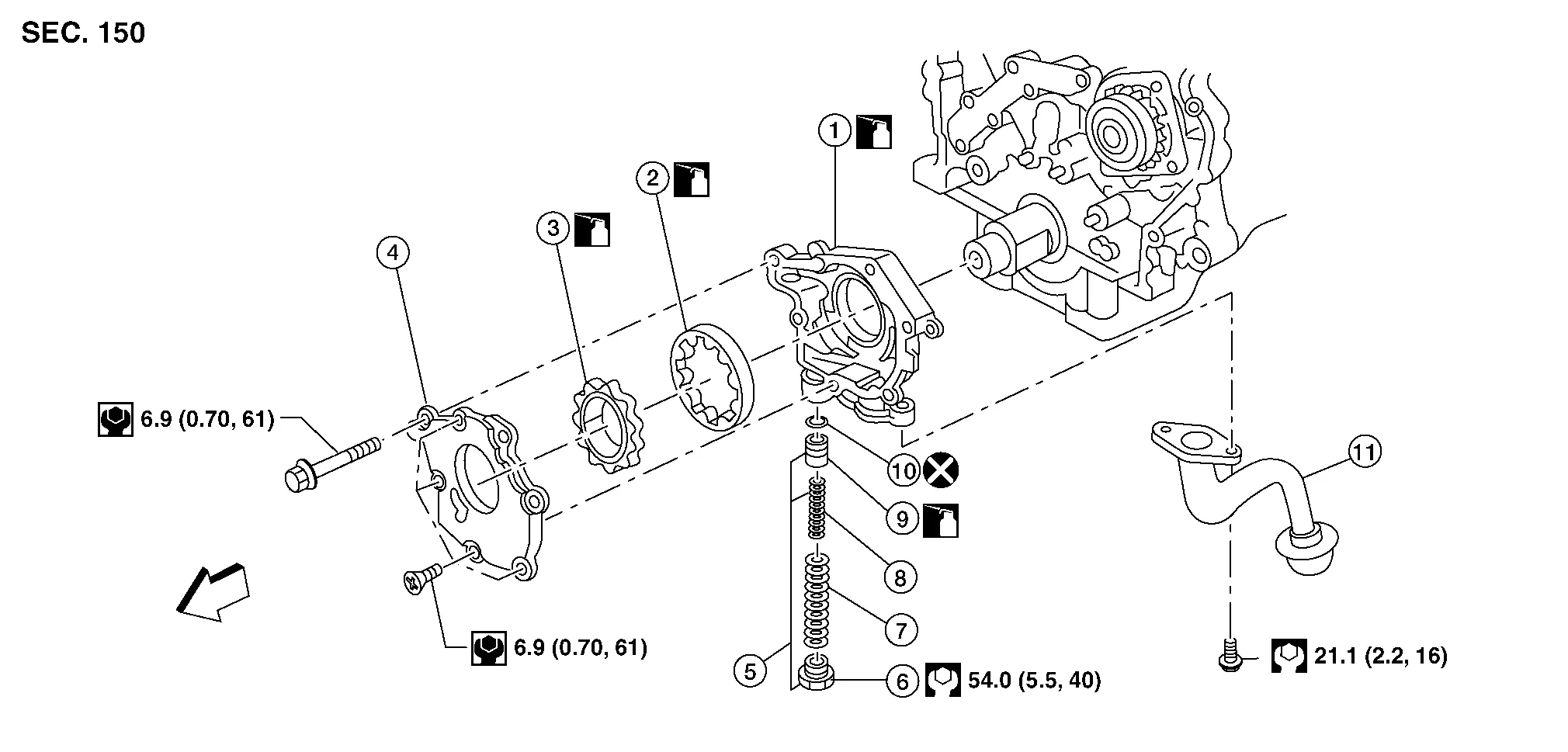
| 1. | Oil pump housing | 2. | Outer pump outer rotor | 3. | Oil pump inner rotor |
| 4. | Oil pump cover | 5. | Regulator valve set assembly | 6. | Regulator valve plug |
| 7. | Regulator valve spring | 8. | Regulator valve spring | 9. | Regulator valve |
| 10. | Regulator valve O-ring | 11. | Oil strainer | Engine front |
CAUTION:
Before assembly, apply new engine oil to the parts as shown.
DISASSEMBLY
Remove the oil pump cover.
Remove inner rotor and outer rotor from oil pump housing.
CAUTION:
The outer rotor has directional vanes in relation to the rotation of the oil pump shaft. Note the outer rotor vane direction for assembly.
Remove oil strainer from oil pump housing.
After removing regulator plug, remove spring and regulator valve.
INSPECTION AFTER DISASSEMBLY
Clearance of Oil Pump Parts
-
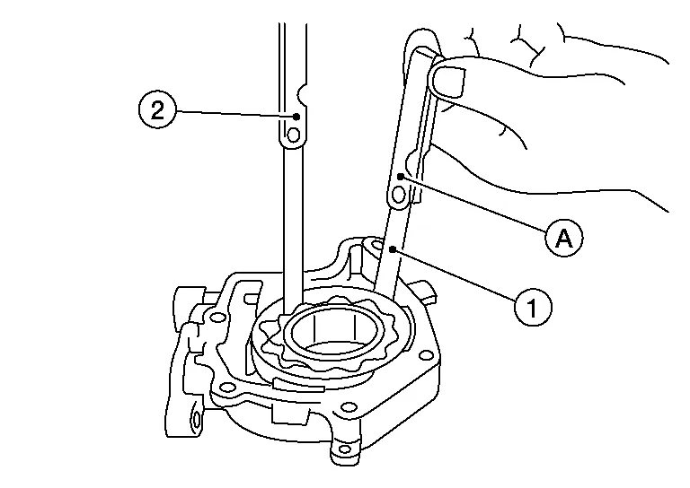
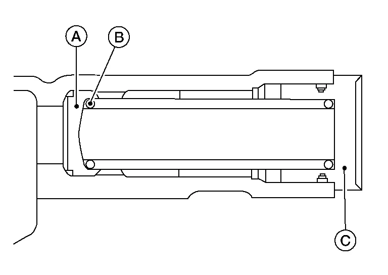
Measure clearance using suitable tool (A).
-
Clearance between outer rotor and oil pump body (position 1).
Standard : Refer to Oil Pump. -
Tip clearance between inner rotor and outer rotor (position 2).
Standard : Refer to Oil Pump.
-
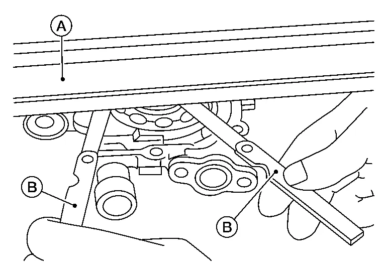
Measure clearance using suitable tools (A/B).
-
Side clearance between inner rotor and oil pump body (position 3).
Standard : Refer to Oil Pump. -
Side clearance between outer rotor and oil pump body (position 4).
| Standard | : Refer to Oil Pump. |
-
Calculate the clearance between inner rotor (1) and oil pump body as follows:
Measure the outer diameter of protruded portion of inner rotor (position A).
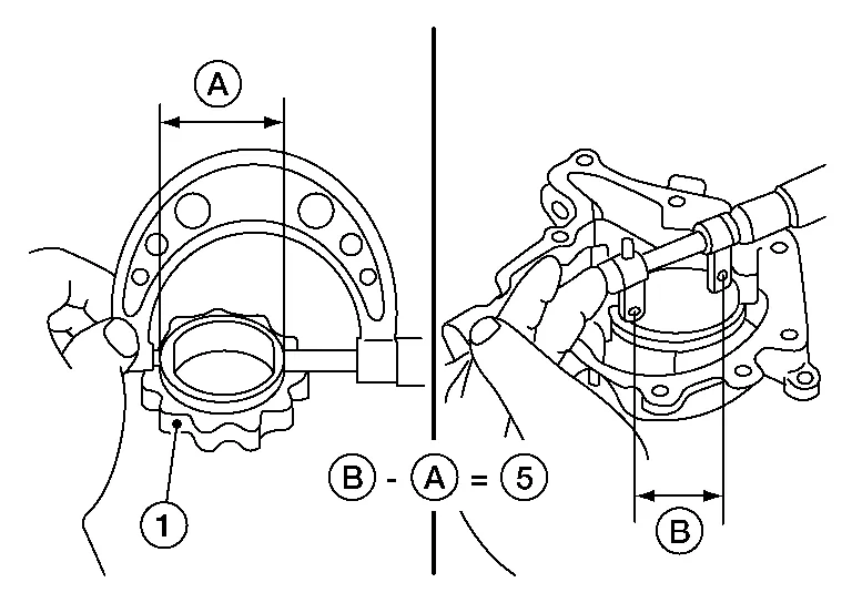
Measure the inner diameter of oil pump body with inside micrometer (position B).
(clearance 5) = (inner diameter of oil pump body B) – (outer diameter of inner rotor A)
| Standard | : Refer to Oil Pump. |
If out of specifications, replace oil pump assembly.
Regulator Valve
Visually inspect components for wear and damage, including regulator plug (C).
Check oil pressure regulator valve (A) sliding surface and valve spring (B).
Coat regulator valve with engine oil. Check that it falls smoothly into the valve hole by its own weight.
If damaged, replace oil pump assembly.
Regulator Valve Clearance
(Clearance 6) = D (Valve hole diameter) – E (Outer diameter of valve)
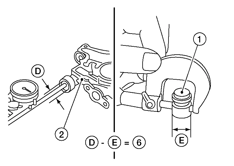
| Standard | : Refer to Regulator Valve. |
| (1) | : Regulatory valve |
| (2) | : Oil pump body |
If it exceeds the standard, replace the oil pump assembly.
CAUTION:
-
Coat regulator valve with engine oil.
-
Check that it falls smoothly into the valve hole by its own weight.
Assembly
Assembly is in the reverse order of disassembly.
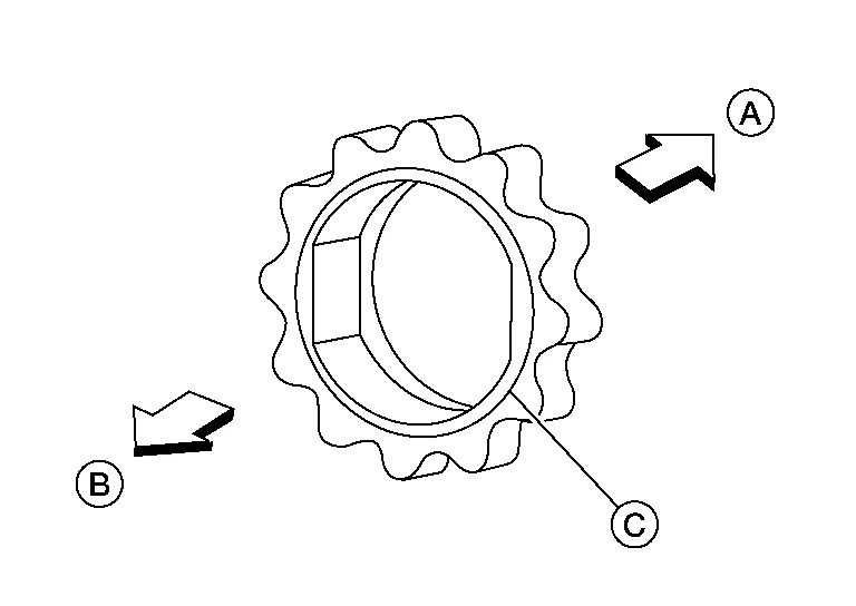
-
Assemble the outer rotor in the correct vane orientation to rotation as noted during disassembly and the inner rotor with the groove on the oil pump cover side.
CAUTION:
-
Do not reuse O-ring.
-
Before assembly apply new engine oil to the parts as specified.
-
| (A) | : Housing side |
| (B) | : Cover side |
| (C) | : Groove |

 Oil Cooler
Exploded View
1.
Connector bolt
2.
Copper gasket
3.
Water drain plug
4.
Water pipe
5.
Bracket
6.
Clamp
7.
Water hose
8...
Other information:
Nissan Murano (Z52) 2015-2024 Owners Manual: Startup display
When the vehicle in placed in theONor ACC position the screens that display in the vehicle information display include: Home Audio Navigation (if so equipped) Drive computer Fuel economy Driving aids (if so equipped) Speed Limit Sign (if so equipped) Tire pressure information Warning review Settings The warnings review title screen will show how many active warnings exist, or “No items to review” in the event that no warnings are active...
Nissan Murano (Z52) 2015-2024 Owners Manual: Front manual seat adjustment (if so equipped)
Your vehicle seats can be adjusted manually. For additional information about adjusting the seats, refer to the steps outlined in this section. Forward and backward Pull the center of the bar up and hold it while you slide the seat forward or backward to the desired position...
Categories
- Manuals Home
- Nissan Murano Owners Manual
- Nissan Murano Service Manual
- Shift lock release
- Passenger compartment
- Jacking up vehicle and removing the damaged tire
- New on site
- Most important about car
Autolight system
The autolight system allows the headlights to turn on and off automatically. The autolight system can:
Turn on the headlights, front parking, tail, license plate and instrument panel lights automatically when it is dark. Turn off all the lights (except daylight running lights) when it is light. Keep all the lights on for a period of time after you place the ignition switch in the OFF position and all doors are closed.