Nissan Murano: Dtc/circuit Diagnosis / Electronic Controlled Engine Mount
CHECK OVERALL FUNCTION
-
Start engine and warm it up to normal operating temperature.
-
Shift selector position is D while depressing the brake pedal and parking brake pedal.
-
Disconnect electronic controlled engine mount control solenoid valve harness connector.
-
Check that body vibration increases compared to the condition of step 2 above (with Nissan Murano vehicle stopped).
Is the inspection result normal?
YES>>INSPECTION END
NO>>Diagnosis Procedure.
CHECK VACUUM SOURCE
-
Turn ignition switch OFF.
-
Reconnect electronic controlled engine mount control solenoid valve harness connector.
-
Disconnect vacuum hose connected to electronic controlled engine mount.
-
Start engine and let it idle.
-
Check vacuum hose for vacuum existence.
Vacuum should exist.
Is the inspection result normal?
YES>>GO TO 7.
NO>>GO TO 2.
CHECK VACUUM HOSES AND VACUUM GALLERY
-
Turn ignition switch OFF.
-
Check vacuum hoses and vacuum gallery for clogging, cracks or improper connection. Refer to System Description.
Is the inspection result normal?
YES>>GO TO 3.
NO>>Repair or replace vacuum hoses and vacuum gallery.
CHECK ELECTRONIC CONTROLLED ENGINE MOUNT CONTROL SOLENOID VALVE POWER SUPPLY
-
Disconnect electronic controlled engine mount control solenoid valve harness connector.
-
Turn ignition switch ON.
-
Check the voltage between front electronic controlled engine mount harness connector and ground.
Electronic controlled engine mount control solenoid valve Ground Voltage Connector Terminal F64 1 Ground Battery voltage
Is the inspection result normal?
YES>>GO TO 4.
NO>>Repair open circuit, short to ground or short to power in harness connectors.
CHECK ELECTRONIC CONTROLLED ENGINE MOUNT CONTROL SOLENOID VALVE OUTPUT SIGNAL CIRCUIT FOR OPEN AND SHORT
-
Disconnect ECM harness connector.
-
Check the continuity between ECM harness connector and electronic controlled engine mount control solenoid valve harness connector.
ECM Electronic controlled engine mount control solenoid valve Continuity Connector Terminal Connector Terminal F78 49 F64 2 Existed -
Also check harness for short to ground and short to power.
Is the inspection result normal?
YES>>GO TO 5.
NO>>Repair open circuit, short to ground or short to power in harness connectors.
CHECK ELECTRONIC CONTROLLED ENGINE MOUNT CONTROL SOLENOID VALVE
Check electronic controlled engine mount control solenoid valve. Refer to Component Inspection.
Is the inspection result normal?
YES>>GO TO 6.
NO>>Replace electronic controlled engine mount control solenoid valve. Refer to Component Parts Location.
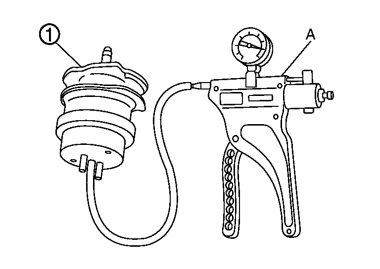
CHECK ELECTRONIC CONTROLLED ENGINE MOUNT
-
Turn ignition switch OFF.
-
Install vacuum pump (A) to electronic controlled engine mount
 .
.
-
Check that a vacuum is maintained when applying the vacuum of -40 kPa (-0.41 kg/cm2, -5.8 psi) to electronic controlled engine mount.
-
Also visually check electronic controlled engine mount.
Is the inspection result normal?
YES>>GO TO 7.
NO>>Replace electronic controlled engine mount.
CHECK INTERMITTENT INCIDENT
Check intermittent incident. Refer to Intermittent Incident.
Is the inspection result normal?
YES>>Replace intake manifold collector. Refer to Removal and Installation.
NO>>Repair or replace error-detected parts.
CHECK ELECTRONIC CONTROLLED ENGINE MOUNT CONTROL SOLENOID VALVE
 With CONSULT
-
Turn ignition switch OFF.
-
Reconnect electronic controlled engine mount control solenoid valve harness connector.
-
Disconnect vacuum hoses connected to electronic controlled engine mount control solenoid valve.
-
Turn ignition switch ON.
-
Select “ENGINE MOUNTING” in “ACTIVE TEST” mode with CONSULT.
-
Check air passage continuity and operation delay time under the following conditions.

Condition
(ENGINE MOUNTING)Air passage continuity between  and
and 
Air passage continuity
between and 
TRVL Existed Not existed IDLE Not existed Existed
 Without CONSULT
-
Turn ignition switch OFF.
-
Disconnect electronic controlled engine mount control solenoid valve harness connector.
-
Disconnect vacuum hoses connected to electronic controlled engine mount control solenoid valve.
-
Check air passage continuity and operation delay time under the following conditions.
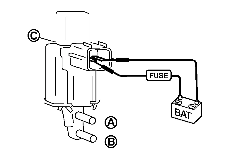
Condition Air passage continuity between and Air passage continuity
between and 12 V direct current supply between terminals 1 and 2 Existed Not existed No supply Not existed Existed
Is the inspection result normal?
YES>>INSPECTION END
NO>>Replace electronic controlled engine mount control solenoid valve. Refer to Component Parts Location.
 Electrical Load Signal
Component Function Check
CHECK REAR WINDOW DEFOGGER SWITCH FUNCTION
Turn ignition switch ON.
Connect CONSULT and select “DATA MONITOR” mode.
Select “LOAD SIGNAL” and check indication under the following conditions...
 Fuel Injector
Component Function Check
INSPECTION START
Turn ignition switch to START.
Are any cylinders ignited?
YES>>
GO TO 2.
NO>>
Proceed to Diagnosis Procedure...
Other information:
Nissan Murano (Z52) 2015-2024 Service Manual: U1010-49 Control Unit (can)
DTC Description DESCRIPTIONCAN controller controls the communication of ITS communication signal and the error detection.DTC DETECTION LOGIC DTC No. CONSULT screen terms (Trouble diagnosis content) DTC detection condition U1010-49 CONTROL UNIT (CAN) [Control unit (CAN)] Diagnosis condition When ignition switch is ON...
Nissan Murano (Z52) 2015-2024 Service Manual: Automatic Drive Positioner :: Precaution. Precautions
Precaution for Supplemental Restraint System (SRS) "AIR BAG" and "SEAT BELT PRE-TENSIONER" The Supplemental Restraint System such as “AIR BAG” and “SEAT BELT PRE-TENSIONER”, used along with a front seat belt, helps to reduce the risk or severity of injury to the driver and front passenger for certain types of collisions...
Categories
- Manuals Home
- Nissan Murano Owners Manual
- Nissan Murano Service Manual
- Settings
- Jacking up vehicle and removing the damaged tire
- Rear bench seat adjustment
- New on site
- Most important about car
Seatback pockets

Theremaybe one or two seatback pockets located on the back of the driver and passenger seats. The pockets can be used to store maps.
WARNING