Nissan Murano: Security Control System :: System Description / Component Parts. Security Control
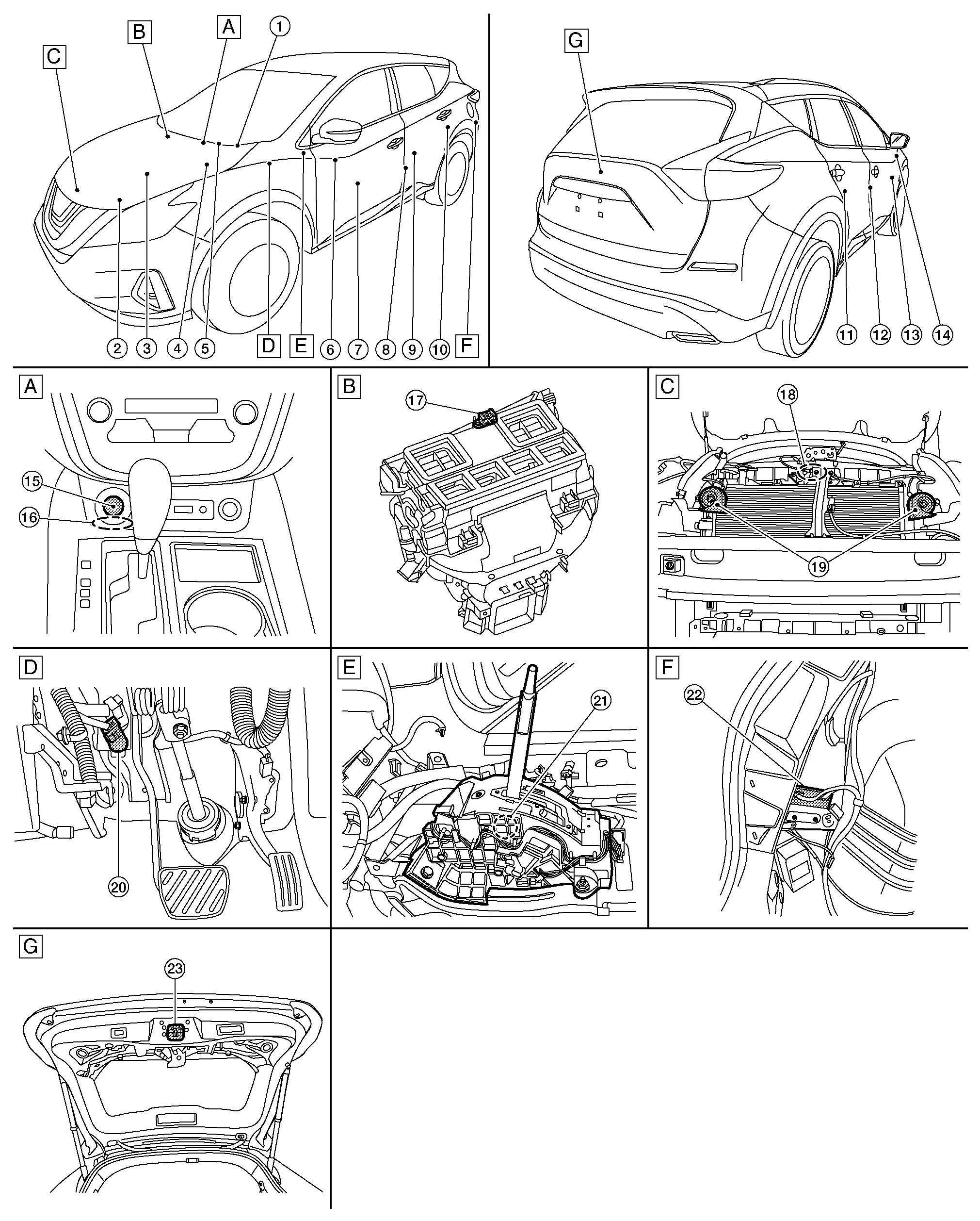
| A. | View of center console | B. | View with heating and cooling unit assembly removed | C. | View with front bumper fascia removed |
| D. | Brake pedal area | E. | Between front seats (view with center console removed) | F. | View with LH luggage side |
| G. | View with back door open |
| No. | Component | Function |
|---|---|---|
| 1. | Combination meter |
|
| 2. | Transmission range switch |
The transmission range switch detects the selector lever position. Refer to Transmission Range Switch for detailed component location. |
| 3. | ECM (Engine Control Module) |
ECM detects the "P" or "N" position from transmission range switch signal. Refer to ECM for detailed component location. |
| 4. | IPDM E/R (Intelligent Power Distribution Module Engine Room) |
IPDM E/R detects push-button ignition switch (push switch) status and transmits push-button ignition switch status signal (CAN) to BCM. Refer to Component Parts Location for detailed component location. |
| 5. | BCM (Body Control Module) |
|
| 6. | Main power window and door lock/unlock switch |
|
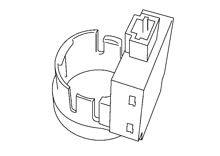
| 7. | Inside key antenna (console) |
Inside key antenna (console) detects whether Intelligent Key is inside the Nissan Murano vehicle or not, and then transmits the signal to the BCM. Refer to Inside Key Antenna (console) for detailed component location. |
| 8. | Front door switch LH |
Front door switch LH transmits door open/closed signal to the BCM. Refer to Front Door Switch for detailed component location. |
| 9. | Inside key antenna (luggage room) |
Inside key antenna (luggage room) detects whether Intelligent Key is inside the Nissan Murano vehicle or not, and then transmits the signal to the BCM. Refer to Inside Key Antenna (luggage room) for detailed component location. |
| 10. | Rear door switch LH |
Rear door switch LH transmits door open/closed signal to the BCM. Refer to Rear Door Switch for detailed component location. |
| 11. | Rear door switch RH |
Rear door switch RH transmits door open/closed signal to the BCM. Refer to Rear Door Switch for detailed component location. |
| 12. | Front door switch RH |
Door switch detects door open/close condition and then transmits ON/OFF signal to BCM. Refer to Front Door Switch for detailed component location. |
| 13. | Power window and door lock/unlock switch RH |
Door lock and unlock switch transmits door lock/unlock operation signal to BCM. Refer to Power Window and Door Lock/Unlock Switch RH for detailed component location. |
| 14. | Remote keyless entry receiver |
Remote keyless entry receiver receives button operation signal and key ID signal of Intelligent Key and then transmits them to BCM. Refer to Remote Keyless Entry Receiver for detailed component location. |
| 15. | Push-button ignition switch |
|
| 16. | NATS antenna amp. | Refer to NATS Antenna Amp.. |
| 17. | Dongle unit (if equipped) | BCM performs ID verification between BCM and dongle unit. When verification result is OK, BCM permits cranking. |
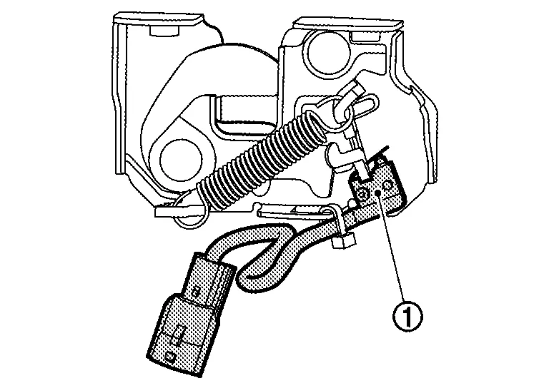
| 18. | Hood switch | Refer to Hood Switch. |
| 19. | Horns (low/high) | IPDM E/R energizes the horns when the security system is activated. |
| 20. | Stop lamp switch |
When the stop lamp switch supplies power to the BCM, the BCM supplies power to the shift lock solenoid. Refer to Stop Lamp Switch for detailed component location. |
| 21 | CVT shift selector (detent switch) |
This switch provides CVT shift selector position to the BCM. Refer to Component Parts Location for detailed component location. |
| 22. | Automatic back door control module (if equipped) | Refer to Automatic Back Door Control Module for detailed component location. |
| 23. | Back door lock assembly |
Back door lock actuator locks/unlocks the back door latch assembly. Refer to Back Door Lock Assembly for detailed component location. |
-
NATS Antenna Amp. is installed behind push-button ignition switch.
-
The ID verification is performed between BCM and transponder integrated into Intelligent Key via NATS antenna amp. when Intelligent Key backside is contacted to power switch, in case that Intelligent Key battery is discharged. If the ID verification result is OK, the operation of power switch is available.
-
Hood switch is integrated into hood lock assembly LH. It is located under the front of hood.
-
Hood switch
 detects that hood is open and then transmits ON/OFF signal to IPDM E/R. IPDM E/R transmits hood switch signal to BCM via CAN communication.

 System
..
Other information:
Nissan Murano (Z52) 2015-2024 Service Manual: Electronic Controlled Engine Mount
System Description SYSTEM DIAGRAMSYSTEM DESCRIPTIONThe ECM controls the engine mount operation corresponding to the engine speed. The control system has a 2-step control [Soft/Hard] Vehicle condition Engine mount control Engine speed: Below 950 rpm Soft Engine speed: Above 950 rpm Hard ELECTRONIC CONTROLLED ENGINE MOUNT LINE DRAWING Electronic controlled engine mount control solenoid valve Intake manifold collector : From next figure Front electronic controlled engine mount Rear electronic controlled engine mount : To previous figure NOTE: Do not use soapy water or any type of solvent while installing vacuum hose...
Nissan Murano (Z52) 2015-2024 Service Manual: Charging System :: Preparation. Preparation
Special Service Tool The actual shape of the tools may differ from those illustrated here. Tool number (TechMate No.) Tool name Description 165-GR8-1200KIT (—) Midtronics Battery Charger and Tester Tests batteries, starting and charging systems and charges batteries...
Categories
- Manuals Home
- Nissan Murano Owners Manual
- Nissan Murano Service Manual
- High Beam Assist (if so equipped)
- How to enable/disable the LDW system
- Jacking up vehicle and removing the damaged tire
- New on site
- Most important about car