Nissan Murano: Dtc/circuit Diagnosis / P2270 Ho2s2
DTC DETECTION LOGIC
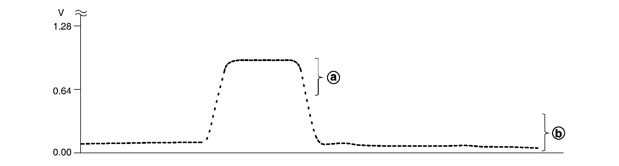
The heated oxygen sensor 2 has a much longer switching time between rich and lean than the air fuel ratio (A/F) sensor 1. The oxygen storage capacity of the three way catalyst (manifold) causes the longer switching time.
MALFUNCTION 1
To judge the malfunctions of heated oxygen sensor 2, ECM monitors whether the voltage is unusually high during various driving conditions such as fuel cut.

 |
: 1.3 V |
MALFUNCTION 2
To judge the malfunctions of heated oxygen sensor 2, ECM monitors whether the minimum voltage of sensor is sufficiently low during various driving conditions such as fuel-cut.

-
An excessively high voltage from the sensor is sent to ECM.
-
The minimum voltage from the sensor is not reached to the specified voltage.
| DTC |
CONSULT screen terms (Trouble diagnosis content) |
DTC detection condition | ||
| P2270 |
O2 sensor signal bank 1 sensor 2 (O2 sensor signal biased/stuck lean bank 1 sensor 2) |
1 | Diagnosis condition | — |
| Signal (terminal) | Voltage signal transmitted from heated oxygen sensor 2 to ECM | |||
| Threshold | An excessively high voltage from the sensor is sent to ECM | |||
| Diagnosis delay time | — | |||
| 2 | Diagnosis condition | — | ||
| Signal (terminal) | Voltage signal transmitted from heated oxygen sensor 2 to ECM | |||
| Threshold | The minimum voltage from the sensor is not reached to the specified voltage | |||
| Diagnosis delay time | — | |||
POSSIBLE CAUSE
P2270 - 1
-
Harness or connectors (The sensor circuit is open or shorted)
-
Heated oxygen sensor 2
P2270 - 2
-
Harness or connectors (The sensor circuit is open or shorted)
-
Heated oxygen sensor 2
-
Fuel pressure
-
Fuel injector
FAIL-SAFE
Not applicable
PRECONDITIONING
If DTC Confirmation Procedure has been previously conducted, always perform the following before conducting the next test.
-
Turn ignition switch OFF and wait at least 10 seconds.
-
Turn ignition switch ON.
-
Turn ignition switch OFF and wait at least 10 seconds.
>>
GO TO 2.
PERFORM DTC CONFIRMATION PROCEDURE FOR MALFUNCTION 1
-
Start engine and warm it up to the normal operating temperature.
-
Turn ignition switch OFF and wait at least 10 seconds.
-
Turn ignition switch ON.
-
Turn ignition switch OFF and wait at least 10 seconds.
-
Start engine and keep the engine speed between 3,500 and 4,000 rpm for at least 1 minute under no load.
-
Let engine idle for 2 minutes.
-
Check 1st trip DTC.
Is 1st trip DTC detected?
YES>>Proceed to Diagnosis Procedure.
NO>>With CONSULT: GO TO 3.
NO>>Without CONSULT: GO TO 5.
PERFORM DTC CONFIRMATION PROCEDURE FOR MALFUNCTION 2
 NOTE:
NOTE:
For better results, perform “DTC WORK SUPPORT” at a temperature of 0 to 30°C (32 to 86°F).
-
Select “DATA MONITOR” mode with CONSULT.
-
Start engine and warm it up to the normal operating temperature.
-
Turn ignition switch OFF and wait at least 10 seconds.
-
Turn ignition switch ON.
-
Turn ignition switch OFF and wait at least 10 seconds.
-
Start engine and keep the engine speed between 3,500 and 4,000 rpm for at least 1 minute under no load.
-
Let engine idle for 1 minute.
-
Check that “COOLANT TEMP/S” indicates more than 70°C (158°F).
If not, warm up engine and go to next step when “COOLANT TEMP/S” indication reaches 70°C (158°F).
-
Open engine hood.
-
Select “HO2S2 (B1) P1146” (for DTC P2270) of “HO2S2” in “DTC WORK SUPPORT” mode with CONSULT.
-
Follow the instruction of CONSULT display.
NOTE:
It will take at most 10 minutes until “COMPLETED” is displayed.
-
Touch “SELF-DIAG RESULTS”.
Which is displayed on CONSULT screen?
OK-1>>To check malfunction symptom before repair: Refer to Intermittent Incident.
OK-2>>Confirmation after repair: INSPECTION END
NG>>Proceed to Diagnosis Procedure.
CON NOT BE DIAGNOSED>>GO TO 4.
PERFORM DTC CONFIRMATION PROCEDURE FOR MALFUNCTION 2 AGAIN
-
Turn ignition switch OFF and leave the Nissan Murano vehicle in a cool place (soak the vehicle).
-
Perform DTC confirmation procedure again.
>>
GO TO 3.
PERFORM COMPONENT FUNCTION CHECK-1
 Without CONSULT
-
Start engine and warm it up to the normal operating temperature.
-
Turn ignition switch OFF and wait at least 10 seconds.
-
Turn ignition switch ON.
-
Turn ignition switch OFF and wait at least 10 seconds.
-
Start engine and keep the engine speed between 3,500 and 4,000 rpm for at least 1 minute under no load.
-
Let engine idle for 1 minute.
-
Check the voltage between ECM harness connector terminals under the following conditions.
ECM Condition Voltage Connector + – Terminal F78 41 35 Revving up to 4,000 rpm under no load at least 10 times The voltage should be below 0.27 V at least once during this procedure.
Is the inspection result normal?
YES>>INSPECTION END
NO>>GO TO 6.
PERFORM COMPONENT FUNCTION CHECK-2
Check the voltage between ECM harness connector terminals under the following conditions.
| ECM | Condition | Voltage | ||
|---|---|---|---|---|
| Connector | + | – | ||
| Terminal | ||||
| F78 | 41 | 35 | Keeping engine speed at idle for 10 minutes | The voltage should be below 0.27 V at least once during this procedure. |
Is the inspection result normal?
YES>>INSPECTION END
NO>>GO TO 7.
PERFORM COMPONENT FUNCTION CHECK-3
Check the voltage between ECM harness connector terminals under the following conditions.
| ECM | Condition | Voltage | ||
|---|---|---|---|---|
| Connector | + | – | ||
| Terminal | ||||
| F78 | 41 | 35 | Coasting from 80 km/h (50 MPH) with selector lever in the D position | The voltage should be below 0.27 V at least once during this procedure. |
Is the inspection result normal?
YES>>To check malfunction symptom before repair: Refer to Intermittent Incident.
YES>>Confirmation after repair: INSPECTION END
NO>>Proceed to Diagnosis Procedure.
INSPECTION START
Confirm the detected malfunction (A or B). Refer to DTC Description.
Which malfunction is detected?
A>>GO TO 2.
B>>GO TO 6.
CHECK HO2S2 CONNECTOR FOR WATER
-
Disconnect heated oxygen sensor 2 harness connector.
-
Check that water is not inside connectors.
Is the inspection result normal?
YES>>GO TO 3.
NO>>Repair or replace harness or connectors.
CHECK HO2S2 GROUND CIRCUIT
-
Disconnect heated oxygen sensor 2 harness connector.
-
Disconnect ECM harness connector.
-
Check the continuity between heated oxygen sensor 2 (HO2S2) harness connector and ECM harness connector.
HO2S2 ECM Continuity Bank Connector Terminal Connector Terminal 1 F62 4 F78 35 Existed -
Also check harness for short to ground and short to power.
Is the inspection result normal?
YES>>GO TO 4.
NO>>Repair open circuit, short to ground or short to power in harness or connectors.
CHECK HO2S2 INPUT SIGNAL CIRCUIT
-
Check the continuity between HO2S2 harness connector and ECM harness connector.
HO2S2 ECM Continuity Bank Connector Terminal Connector Terminal 1 F62 3 F78 41 Existed -
Check the continuity between HO2S2 harness connector and ground, or ECM harness connector and ground.
HO2S2 Ground Continuity Bank Connector Terminal 1 F62 3 Ground Not existed ECM Ground Continuity Connector Terminal F78 41 Ground Not existed -
Also check harness for short to power.
Is the inspection result normal?
YES>>GO TO 5.
NO>>Repair open circuit, short to ground or short to power in harness or connectors.
CHECK HEATED OXYGEN SENSOR 2
Check heated oxygen sensor 2. Refer to Component Inspection.
Is the inspection result normal?
YES>>INSPECTION END
NO>>Replace malfunctioning heated oxygen sensor 2. Refer to Removal and Installation (bank 1).
CLEAR MIXTURE RATIO SELF-LEARNING VALUE
-
Clear the mixture ratio self-learning value. Refer to Description.
-
Run engine for at least 10 minutes at idle speed.
Is the 1st trip DTC P0172 detected? Is it difficult to start engine?
YES>>Perform trouble diagnosis for DTC P0172. Refer to DTC Description.
NO>>GO TO 7.
CHECK HO2S2 GROUND CIRCUIT
-
Turn ignition switch OFF.
-
Disconnect heated oxygen sensor 2 harness connector.
-
Disconnect ECM harness connector.
-
Check the continuity between HO2S2 harness connector and ECM harness connector.
HO2S2 ECM Continuity Bank Connector Terminal Connector Terminal 1 F62 4 F78 35 Existed -
Also check harness for short to ground and short to power.
Is the inspection result normal?
YES>>GO TO 8.
NO>>Repair open circuit, short to ground or short to power in harness or connectors.
CHECK HO2S2 INPUT SIGNAL CIRCUIT
-
Check the continuity between HO2S2 harness connector and ECM harness connector.
HO2S2 ECM Continuity Bank Connector Terminal Connector Terminal 1 F62 3 F78 41 Existed -
Check the continuity between HO2S2 harness connector and ground, or ECM harness connector and ground.
HO2S2 Ground Continuity Bank Connector Terminal 1 F62 3 Ground Not existed ECM Ground Continuity Connector Terminal F78 41 Ground Not existed -
Also check harness for short to power.
Is the inspection result normal?
YES>>GO TO 9.
NO>>Repair open circuit, short to ground or short to power in harness or connectors.
CHECK HEATED OXYGEN SENSOR 2
Check heated oxygen sensor 2. Refer to Component Inspection
Is the inspection result normal?
YES>>INSPECTION END
NO>>Replace malfunctioning heated oxygen sensor 2. Refer to Removal and Installation (bank 1).
INSPECTION START
Will CONSULT be used?
Will CONSULT be used?
YES>>GO TO 2.
NO>>GO TO 3.
CHECK HEATED OXYGEN SENSOR 2
 With CONSULT
-
Turn ignition switch ON and select “DATA MONITOR” mode with CONSULT.
-
Start engine and warm it up to the normal operating temperature.
-
Turn ignition switch OFF and wait at least 10 seconds.
-
Start engine and keep the engine speed between 3,500 and 4,000 rpm for at least 1 minute under no load.
-
Let engine idle for 1 minute.
-
Select “FUEL INJECTION” in “ACTIVE TEST” mode, and select “HO2S2 (B1)/(B2)” as the monitor item with CONSULT.
-
Check “HO2S2 (B1)/(B2)” at idle speed when adjusting “FUEL INJECTION” to ± 25%.
: The voltage should be above 0.72 V at least on time. 
: The voltage should be below 0.27 V at least on time. “HO2S2 (B1)/(B2)” should be above 0.72 V at least once when the “FUEL INJECTION” is + 25%.
“HO2S2 (B1)/(B2)” should be below 0.27 V at least once when the “FUEL INJECTION” is − 25%.
Is the inspection result normal?
YES>>INSPECTION END
NO>>Replace malfunctioning heated oxygen sensor 2. Refer to Removal and Installation (bank 1).
CHECK HEATED OXYGEN SENSOR 2-I
Without CONSULT
-
Start engine and warm it up to the normal operating temperature.
-
Turn ignition switch OFF and wait at least 10 seconds.
-
Start engine and keep the engine speed between 3,500 and 4,000 rpm for at least 1 minute under no load.
-
Let engine idle for 1 minute.
-
Check the voltage between ECM harness connector terminals under the following conditions.
ECM Condition Voltage Connector + – Terminal F78 41 35 Revving up to 4,000 rpm under no load at least 10 times The voltage should be above 0.72 V at least once during this procedure.
The voltage should be below 0.27 V at least once during this procedure.
Is the inspection result normal?
YES>>INSPECTION END
NO>>GO TO 4.
CHECK HEATED OXYGEN SENSOR 2-II
Check the voltage between ECM harness connector terminals under the following conditions.
| ECM | Condition | Voltage | ||
|---|---|---|---|---|
| Connector | + | – | ||
| Terminal | ||||
| F78 | 41 | 35 | Keeping engine at idle for 10 minutes |
The voltage should be above 0.72 V at least once during this procedure. The voltage should be below 0.27 V at least once during this procedure. |
Is the inspection result normal?
YES>>INSPECTION END
NO>>GO TO 5.
CHECK HEATED OXYGEN SENSOR 2-III
Check the voltage between ECM harness connector terminals under the following conditions.
| ECM | Condition | Voltage | ||
|---|---|---|---|---|
| Connector | + | – | ||
| Terminal | ||||
| F78 | 41 | 35 | Coasting from 80 km/h (50 MPH) with selector lever in the D position |
The voltage should be above 0.72 V at least once during this procedure. The voltage should be below 0.27 V at least once during this procedure. |
Is the inspection result normal?
YES>>INSPECTION END
NO>>Replace malfunctioning heated oxygen sensor 2. Refer to Removal and Installation (bank 1).
 P2256 A/f Sensor 1
DTC Description
DTC DETECTION LOGICTo judge malfunctions, the diagnosis checks that the A/F signal computed by ECM from the A/F sensor 1 signal fluctuates according to fuel feedback control...
 P2271 Ho2s2
DTC Description
DTC DETECTION LOGICThe heated oxygen sensor 2 has a much longer switching time between rich and lean than the air fuel ratio (A/F) sensor 1...
Other information:
Nissan Murano (Z52) 2015-2024 Service Manual: U1010-49 Control Unit(can)
DTC Description DESCRIPTIONCAN (Controller Area Network) is a serial communication line for real-time application. It is an on-Nissan Murano vehicle multiplex communication line with high data communication speed and excellent error detection ability...
Nissan Murano (Z52) 2015-2024 Owners Manual: Automatic Emergency Braking (AEB) (if so equipped)
WARNING Failure to follow the warnings and instructions for proper use of the AEB system could result in serious injury or death. The AEB system is a supplemental aid to the driver. It is not a replacement for the driver’s attention to traffic conditions or responsibility to drive safely...
Categories
- Manuals Home
- Nissan Murano Owners Manual
- Nissan Murano Service Manual
- Settings
- Memory storage function (key-link)
- Tire rotation
- New on site
- Most important about car
Vehicle security system

Your vehicle has two types of security systems:
Vehicle security system NISSAN Vehicle Immobilizer SystemThe vehicle security system provides visual and audible alarm signals if someone opens the doors, liftgate or the hood when the system is armed. It is not, however, a motion detection type system that activates when a vehicle is moved or when a vibration occurs.